
 EN
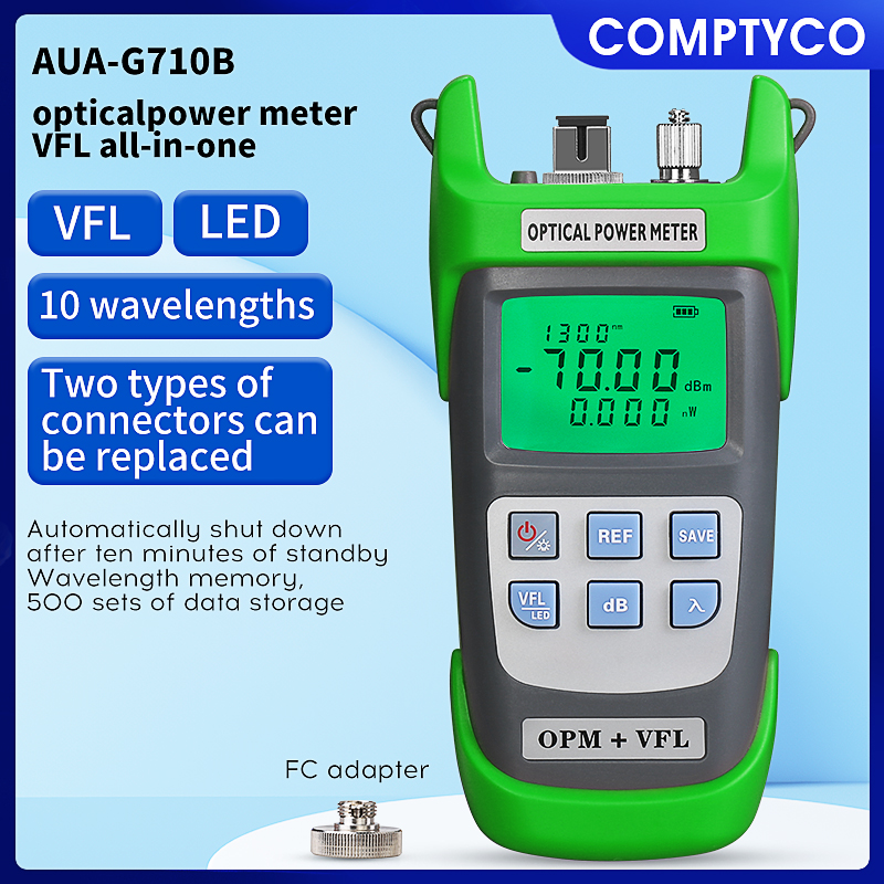
End-to-end link loss testing represents one of the most critical procedures in fiber optic network deployment and maintenance. The accuracy of these measurements directly impacts network performance, reliability, and long-term operational costs. An optical power meter stands as the primary instrument for this essential testing process, enabling technicians and engineers to quantify signal attenuation across fiber optic links with precision and confidence. Without proper optical power meter measurements, network operators cannot accurately diagnose performance issues, validate installation quality, or ensure compliance with industry standards.
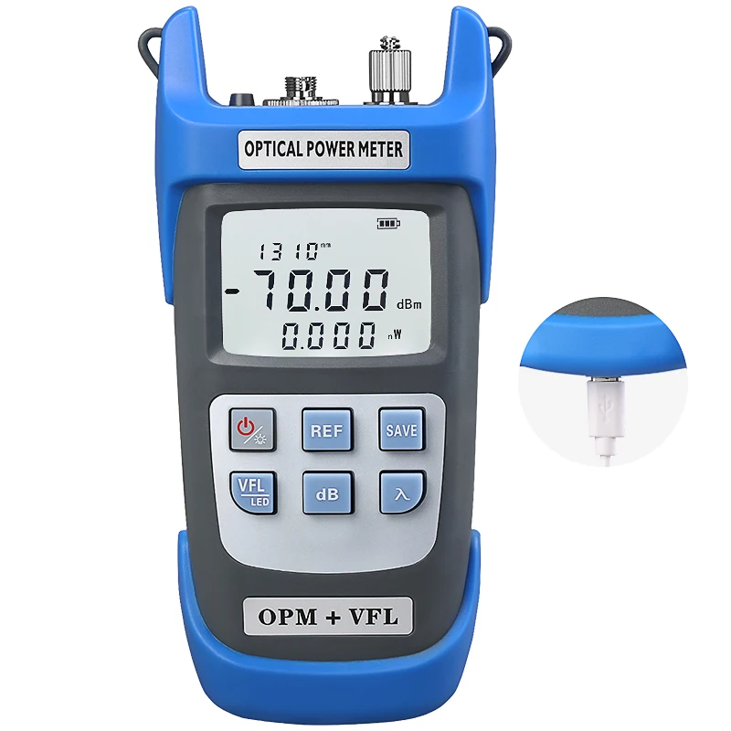
The fundamental role of an optical power meter in link loss testing involves measuring transmitted and received optical signal power levels at specific points throughout a fiber optic communication path. By comparing these measurements, technicians establish baseline performance data and identify where signal degradation occurs. An optical power meter equipped with appropriate wavelength sensitivity provides the foundation for comprehensive link budget analysis, troubleshooting network faults, and documenting installation compliance with telecommunications standards such as TIA-568 and IEC 61280 specifications.
Understanding Optical Power Meter Functionality in Link Loss Assessment
Core Measurement Capabilities of an Optical Power Meter
An optical power meter measures light intensity transmitted through fiber optic cables by detecting photons and converting them into electrical signals. The device quantifies power in decibels relative to one milliwatt (dBm), providing standardized metrics for comparing different link segments. Modern optical power meter designs incorporate multiple wavelength detection capabilities, allowing simultaneous measurement of 850 nanometer, 1310 nanometer, and 1550 nanometer signals commonly used in telecommunications and data center applications. The optical power meter's sensitivity range typically spans from negative 70 dBm to positive 10 dBm, encompassing both weak attenuated signals and strong local transmissions.
Precision represents a critical characteristic of any optical power meter used for link loss testing. High-accuracy optical power meter instruments maintain calibration within ±0.5 dB across their operating range, enabling reliable comparison of measurements taken at different times or by different technicians. An optical power meter with inadequate precision can mask installation defects, overestimate network capacity, or create false alarms regarding performance degradation. Battery-powered optical power meter designs provide field flexibility, while rechargeable optical power meter models reduce operational costs over extended deployment periods.
Signal Loss Measurement Methodology Using an Optical Power Meter
Effective link loss testing requires systematic measurement protocols using an optical power meter at multiple reference points. Technicians first measure the transmitted signal power at the source using their optical power meter, establishing a baseline reading. The same optical power meter then measures received power at the far end of the fiber link, with the difference between these readings representing total link loss. An optical power meter baseline measurement taken immediately after installation provides a reference standard for future optical power meter comparisons, enabling early detection of performance degradation caused by environmental stress, connector corrosion, or fiber damage.
Intermediate optical power meter measurements between link segments isolate problem areas within complex networks. By measuring optical power meter readings at patch panels, splice points, and amplifier stages, technicians pinpoint where excessive loss occurs and take corrective action. An optical power meter used systematically throughout the testing process creates a complete power level map of the fiber optic infrastructure. This comprehensive optical power meter data enables network planners to optimize amplifier placement, identify marginal link segments requiring reinforcement, and plan capacity upgrades based on actual performance metrics rather than theoretical calculations.
Practical Applications and Link Loss Testing Scenarios
Long-Distance Telecommunications Deployments
Telecommunications carriers rely heavily on optical power meter technology for validating long-distance fiber routes spanning hundreds of kilometers. Each optical power meter reading at intermediate repeater stations confirms that signal regeneration occurs at appropriate power levels. An optical power meter verifies that amplifier gain exactly compensates for expected fiber attenuation, preventing both signal underpowering and dangerous optical overdriving that damages receiver components. For regional network expansion projects, optical power meter documentation proves compliance with carrier performance standards and supports handoff procedures between construction crews and operational teams.
Data Center Interconnect Testing and Monitoring
Data center environments demand precise optical power meter measurements to ensure uninterrupted communication between server farms and storage systems. An optical power meter validates that each data center interconnect link meets stringent power budget requirements, typically requiring measurements within a narrow range around specified nominal levels. High-speed data transmission standards such as 100 Gigabit Ethernet impose tight optical power meter tolerances, where even one decibel deviation can compromise link stability. Optical power meter readings taken during commissioning create baseline documentation that support troubleshooting when performance issues emerge months or years after initial deployment.
Advanced Optical Power Meter Features Supporting Link Loss Testing
Integrated Visual Fault Locator and Multifunction Capabilities
Modern optical power meter instruments increasingly integrate additional testing functions that enhance link loss assessment efficiency. An optical power meter with integrated visual fault locator capability identifies fiber breaks and severe bends through visible light emission, allowing technicians to address physical damage before conducting optical power meter measurements. An optical power meter featuring an integrated light source eliminates the need for separate test equipment in basic link loss scenarios, reducing field kit weight and improving technician productivity. Some advanced optical power meter designs incorporate optical return loss measurement, enabling comprehensive characterization of connector quality alongside optical power meter loss measurements.
Data Logging and Remote Monitoring Capabilities
Advanced optical power meter models support automated data collection and historical trend analysis essential for ongoing network monitoring. An optical power meter with integrated data logging automatically timestamps and records optical power meter readings, creating audit trails that demonstrate compliance with maintenance standards. Optical power meter systems that export measurements to network management software enable technicians to correlate optical power meter data with other performance indicators such as error rates and latency metrics. Remote optical power meter monitoring systems alert technicians immediately when measurements drift outside acceptable ranges, enabling proactive maintenance before customer-impacting service degradation occurs.
Best Practices for Optical Power Meter Deployment in Link Loss Testing
Calibration, Training, and Documentation Standards
Proper optical power meter operation requires regular calibration to maintain measurement accuracy. Industry standards recommend optical power meter calibration verification at least annually, with more frequent checks in high-volume testing environments. An optical power meter technician should understand wavelength-specific measurement characteristics and connector type variations that affect readings. Comprehensive documentation of optical power meter procedures, acceptable measurement ranges, and corrective action thresholds ensures consistent testing practices across multiple technicians and locations.
Training programs for optical power meter use must address connector cleanliness effects, as microscopic dust particles significantly impact optical power meter accuracy. An optical power meter operator should verify connector end-face condition before each measurement, using lint-free wipes and approved cleaning solutions. Optical power meter users need to understand differential wavelength loss characteristics in fiber, where longer wavelengths experience less attenuation than shorter wavelengths across identical distances. Proper optical power meter training emphasizes measurement repeatability, recognizing that consistent results across multiple optical power meter tests provide greater confidence than individual readings regardless of absolute values.
Integration with Comprehensive Network Testing Workflows
Link loss testing using an optical power meter represents just one component of comprehensive fiber optic network validation. Technicians should sequence optical power meter measurements after visual inspection, continuity verification, and preliminary visual fault locator assessment to ensure efficient troubleshooting workflows. Optical power meter results should be correlated with optical time domain reflectometer findings, which identify specific attenuation locations along fiber spans. An optical power meter combined with bi-directional measurements captures asymmetric performance that might indicate directional issues such as unidirectional connector contamination or directional amplifier failures.
FAQ
Why is an optical power meter essential for validating new fiber optic installations?
An optical power meter provides objective, quantifiable evidence that fiber optic installations meet design specifications and industry standards before handoff to operational teams. Optical power meter measurements document baseline performance for future reference, establish compliance records for regulatory requirements, and identify defective components during commissioning when repairs prove less expensive than emergency maintenance. Without optical power meter validation data, carriers and enterprises cannot confidently predict long-term network reliability or troubleshoot emerging performance problems effectively.
How does an optical power meter distinguish between different fiber attenuation causes?
An optical power meter alone cannot identify specific attenuation causes but provides the numerical data foundation for diagnostic interpretation. Technicians combine optical power meter readings with visual fault locator results, documentation of link geometry, and historical baseline comparisons to isolate whether loss stems from fiber quality issues, excessive bending, connector problems, or environmental degradation. An optical power meter showing uniform loss across all wavelengths suggests natural fiber attenuation, while wavelength-dependent optical power meter variations might indicate connector oxidation or selective scattering from specific defects.
What optical power meter specifications matter most for telecommunications link testing applications?
Telecommunications link testing prioritizes optical power meter accuracy, wavelength coverage spanning 850 nanometers through 1625 nanometers, and stable battery operation throughout extended field deployment days. An optical power meter with ±0.5 dB accuracy and automatic wavelength identification simplifies technician workflows and reduces measurement errors. Data logging capability in an optical power meter enables comprehensive documentation required for carrier certification processes, while rechargeable battery technology reduces operating costs compared to disposable alternatives.