
 EN
EN
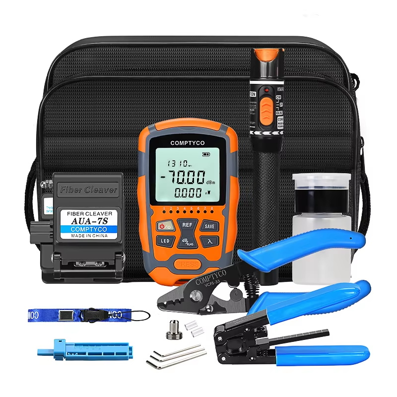
Working inside a congested cable tray is one of the most frustrating challenges any fiber technician faces. Dozens of cables run in parallel, labels fade over time, and a single misidentified fiber can trigger hours of troubleshooting. This is exactly where a visual fault locator becomes an indispensable field tool. By injecting a visible red laser into the fiber core, it allows you to trace, identify, and verify individual fibers without expensive OTDR equipment or guesswork.
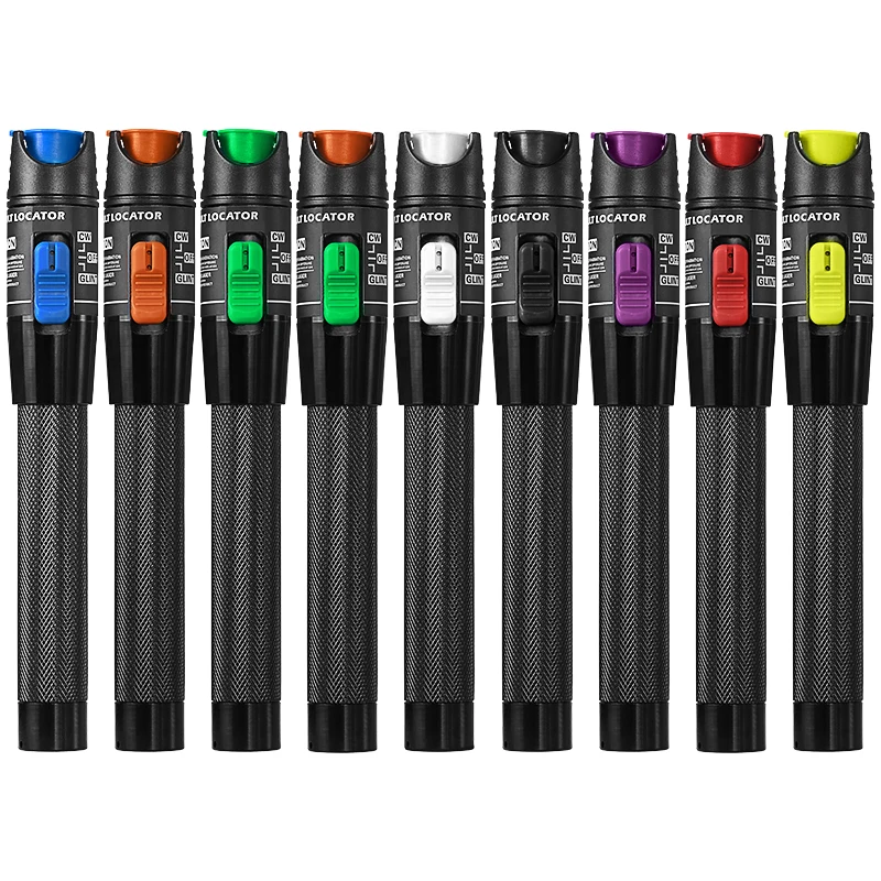
Understanding how to use a visual fault locator correctly in dense cable environments is a skill that separates efficient technicians from those who spend unnecessary time chasing phantom faults. This guide walks through the complete process — from physical setup to systematic tracing technique — so you can confidently work through even the most congested cable tray scenarios. Whether you are managing a data center backbone, a building riser, or an industrial fiber run, the method described here applies directly to real field conditions.
Understanding What a Visual Fault Locator Does in a Dense Fiber Environment
The Core Mechanism Behind the Red Light
A visual fault locator works by coupling a highly focused red laser — typically at 650 nm wavelength — directly into the fiber core through a standard connector interface. Once inside the fiber, the light travels along the glass core and remains contained by total internal reflection under normal conditions. When the fiber is bent beyond its minimum bend radius, broken, or improperly spliced, the light escapes the cladding and becomes visible to the naked eye.
This escaped light is the key to tracing in congested cable trays. In a densely packed environment, you are not necessarily looking for fault emission — you are using the red glow visible at the far end of the fiber to confirm you have the correct strand. The visual fault locator essentially turns an invisible signal path into a visible one, removing the ambiguity that makes congested tray work so difficult.
Most modern visual fault locator devices cover distances from 1 km up to 50 km depending on output power, but in a cable tray scenario, you typically work within a single building or floor. Short-range precision matters far more than long-distance reach in this use case, so selecting a unit with stable continuous-wave and pulse modes gives you more control during close-range fiber identification work.
Why Congested Cable Trays Create Unique Tracing Challenges
In a sparse installation, tracing a fiber is relatively straightforward. In a congested tray, however, cables from multiple installations, multiple vendors, and multiple eras are often bundled together. Color coding systems may differ between cable batches, outer jacket colors may have faded, and fiber labeling at patch panels may no longer match the physical routing due to reroutes or repairs done over time.
The congestion also introduces a practical problem: when you inject light with a visual fault locator at one end, you need someone or a camera positioned at the other end to observe the red glow at the connector face. In a crowded tray with tight bend radii at both ends, physically accessing and inspecting connectors becomes a coordination task in itself. Knowing the proper workflow in advance reduces the time spent repositioning and second-guessing which fiber is glowing.
Additionally, tight bundling in cable trays can cause macro-bending losses on multiple adjacent fibers simultaneously. A visual fault locator can reveal these stress points as faint red glows along the outer jacket, which helps you identify not just the target fiber but also potential performance issues in neighboring cables — a secondary benefit that is easy to overlook but practically valuable.
Preparing the Visual Fault Locator and the Work Environment
Selecting the Right Output Mode for Tracing
A visual fault locator typically offers two operating modes: continuous wave (CW) and pulsed. For fiber identification in a cable tray, the pulsed mode is usually more effective. The blinking red light is easier to distinguish from ambient reflections or from light leakage on adjacent fibers under high ambient lighting conditions. Continuous mode is better suited for pinpointing a specific fault location along a short run because the constant illumination makes subtle leakage more visible.
Before you begin, confirm that your visual fault locator's output power matches the expected fiber length and the sensitivity needed for identification. A 1 mW unit works well for patch cord verification and short intra-rack runs. For longer runs through building risers or inter-floor trays, a 10 mW or higher unit gives you the light intensity needed to see a clear glow at the far connector even when the fiber has moderate bending loss accumulated along the route.
Check the connector adapter on your visual fault locator. Most units come with a universal adapter that accepts SC, FC, and ST connectors directly, with LC connectors requiring a small adapter sleeve. Confirm this before climbing a ladder or reaching into a tray, since a connector mismatch discovered mid-task costs time and disrupts your workflow.
Setting Up a Two-Person or Remote Observation Method
The most reliable tracing method in a congested cable tray uses two people. One technician injects the red laser using the visual fault locator at the source end — typically the patch panel or splice enclosure — while the second technician observes connector faces at the destination end, either at another patch panel, an outlet, or a splice tray. This two-point method eliminates the ambiguity of trying to work alone across a long run.
If working alone, you can use a simple inspection camera or even a smartphone camera pointed at the connector row. Camera sensors are slightly more sensitive to the 650 nm red wavelength than the human eye under bright ambient light, making it easier to spot the glowing connector face even in a busy data center environment. Some technicians use small inspection mirrors angled at the connector row when physical access is limited.
Communication is essential during two-person tracing. Using a hands-free radio or a phone call keeps both technicians coordinated without requiring one person to shout across a facility. Agree on a clear signal protocol before starting — for example, the injection technician activates the visual fault locator on command, and the observation technician confirms the lit fiber by number or label position rather than by color alone.
Step-by-Step Fiber Tracing Process in a Congested Tray
Injecting Light at the Source End
Start by cleaning the connector on the fiber you intend to trace. Even in a busy tray environment, connector contamination affects how well the visual fault locator couples light into the fiber. A dirty connector face scatters the laser and reduces the intensity visible at the far end. A quick clean with a one-click cleaner or a dry IEC-grade wipe takes less than ten seconds and significantly improves tracing reliability.
Insert the cleaned connector into the visual fault locator's adapter port firmly. Most adapters have a small detent or spring-loaded mechanism that confirms full engagement. Activate the device in pulsed mode first. If you are working at a patch panel, note the exact panel port position — row number and column number — so the observation technician knows the starting search zone. Do not assume the observation technician can identify the fiber from the source side description alone.
In some congested tray situations, light from the visual fault locator leaks slightly at tight bends immediately after the injection point. This is normal for high-power units or fibers with existing micro-damage. Note the location of any visible leakage points along the tray surface, as these represent stress points worth documenting even if they do not affect current performance. The visual fault locator is doing double duty here — confirming fiber identity and revealing tray-induced stress simultaneously.
Confirming the Fiber at the Destination End
At the destination end, the observation technician looks directly at the connector end-faces in the panel or splice tray. The fiber carrying the visual fault locator signal glows clearly red at the connector face or, if the connectors are mated, a faint red glow appears around the adapter sleeve. Under low ambient light, this is easily visible. Under bright fluorescent lighting, the camera-assisted method improves contrast significantly.
Once the correct fiber is confirmed, label it immediately at both ends before removing the visual fault locator. This is a critical discipline that many technicians skip under time pressure, which leads to repeating the same tracing work later. Use a permanent label with the circuit ID, port identifier, and date at minimum. In a congested tray environment, self-laminating labels that wrap around the fiber close to the connector are more durable than adhesive flag labels that peel off over time.
If the observation technician cannot identify a clearly glowing fiber despite the visual fault locator being active, there are two likely causes: the fiber has a severe break somewhere along the run that is stopping light propagation, or the connectors at the destination end are not the correct termination for that fiber. In either case, switch the visual fault locator to continuous wave mode and walk the cable tray route looking for visible red leakage from a break point or tight bend that is stopping light from reaching the far end.
Handling Multiple Adjacent Fibers and Bundle Tracing
In a multi-fiber bundle or ribbon cable situation, each individual fiber within the bundle must be traced separately if they are unjacketed or share a common outer tube. The visual fault locator can only inject light into one fiber at a time through a single connector, so systematic sequencing is necessary. Work methodically from position one to the last fiber in the bundle, confirming and labeling each one before moving to the next.
When dealing with loose-tube cables containing multiple fibers, be aware that buffer tube color coding inside the cable should correlate with the standard color sequence, but physical verification with the visual fault locator is always the authoritative method. Color coding standards vary between manufacturers and older installations may not follow current conventions consistently.
For very dense installations with hundreds of fibers in a single tray segment, consider tracing in zones rather than one fiber at a time from end to end. Identify the tray zone where a specific circuit is expected to run based on documentation, then use the visual fault locator only within that confirmed zone. This reduces the observation search area significantly and speeds up the overall tracing process without sacrificing accuracy.
Interpreting Visual Fault Locator Signals During Tray Work
Reading Fault Signatures Along the Fiber Route
A visual fault locator does more than confirm identity. As you trace the fiber route through the tray, the character of any light leakage tells you about the condition of the fiber. A bright, localized red spot at a specific point in the tray indicates a physical fault — a break, a severe bend, or a crushed section where the fiber has been damaged by cable weight or improper management hardware.
A diffuse glow spread over a section of tray typically indicates a macro-bend condition where the cable radius is tighter than the fiber's minimum bend radius specification. This does not always cause immediate loss at acceptable levels, but it creates a vulnerability point. Documenting these zones with your visual fault locator inspection gives maintenance teams actionable data for future tray reorganization or load balancing.
A sudden complete absence of light beyond a certain point in the run — with no visible leakage — combined with no glow at the far connector confirms a complete fiber break or a severely crushed section that has prevented total internal reflection entirely. In this case, the visual fault locator has not only confirmed the fiber identity problem but also localized the approximate fault zone, which dramatically shortens the repair diagnostic process compared to working blind.
Distinguishing Real Faults from Tray-Induced Stress
One nuance that experienced technicians develop over time is the ability to distinguish between a permanent fault and a temporary stress condition revealed by the visual fault locator. In a congested tray, fibers under moderate compressive load from cable weight may show faint leakage under high-power visual fault locator injection but perform within acceptable loss parameters during normal transmission. This does not mean the condition is harmless — it means it is a marginal condition worth monitoring.
If a fiber shows light leakage at a bend point during visual fault locator testing but passes OTDR insertion loss measurements within spec, document both results. The visual fault locator is revealing a physical stress that the OTDR is not sensitive enough to classify as a fault at current traffic levels. Under temperature cycling, vibration, or increased fiber count in the tray, that marginal condition may develop into a real fault. Early documentation is the difference between proactive maintenance and reactive emergency repair.
The visual fault locator is particularly valuable in this dual role — fiber identification tool and preliminary fault survey instrument — precisely because it provides qualitative physical feedback that no electronic test instrument can replicate. Seeing a red glow at a tight bend gives you spatial and physical information about cable routing quality that OTDR traces alone cannot convey.
FAQ
Can I use a visual fault locator on single-mode and multimode fibers equally?
Yes. A visual fault locator works on both single-mode and multimode fibers, though coupling efficiency differs. Single-mode fibers have a much smaller core, so the laser couples with a tighter beam and produces a cleaner, more visible far-end glow. Multimode fibers accept the laser light more easily due to the larger core, which can actually result in slightly less dramatic far-end glow intensity at long ranges. For typical cable tray tracing distances within a building, both fiber types respond well to a standard visual fault locator.
How do I trace a fiber if both ends are already mated in active connectors?
You must disconnect the fiber from its active equipment at the injection end before connecting the visual fault locator. Injecting laser light into an active transceiver port can damage the optical receiver in that equipment. Always confirm the port is disconnected from live equipment before connecting your visual fault locator. At the observation end, a mated connector will show a faint red glow around the adapter sleeve or at any exposed ferrule surface, which is usually sufficient for identification without full disconnection on that side.
What causes the visual fault locator light to disappear before reaching the far end?
Several conditions can stop the light from reaching the observation end. The most common are a complete fiber break, a severely crushed or kinked section in the cable tray, a failed splice joint with high reflectance, or a contaminated connector causing excessive back-reflection at the injection point. Walk the cable route with the visual fault locator active in continuous mode to locate the point where light leakage stops, which marks the approximate fault location. This is one of the most practical advantages of the visual fault locator compared to electronic instruments in a tray environment.
How far can a visual fault locator trace a fiber through a building installation?
For fiber identification purposes — observing the glow at the far connector — a 1 mW to 5 mW visual fault locator covers most intra-building runs up to several hundred meters without difficulty, assuming the fiber is intact and connectors are clean. Higher output units rated at 10 mW to 50 mW extend this range and are more effective when working through trays with multiple bends or slightly dirty connectors. For fault localization rather than simple identification, the visible red leakage from a fault is detectable at shorter distances regardless of total run length, since you are looking at the fault point rather than the far end.
Table of Contents
- Understanding What a Visual Fault Locator Does in a Dense Fiber Environment
- Preparing the Visual Fault Locator and the Work Environment
- Step-by-Step Fiber Tracing Process in a Congested Tray
- Interpreting Visual Fault Locator Signals During Tray Work
-
FAQ
- Can I use a visual fault locator on single-mode and multimode fibers equally?
- How do I trace a fiber if both ends are already mated in active connectors?
- What causes the visual fault locator light to disappear before reaching the far end?
- How far can a visual fault locator trace a fiber through a building installation?


