Network technicians face constant pressure to quickly identify and resolve fiber optic issues that can cripple business operations. When fiber breaks or excessive bends occur in optical networks, traditional troubleshooting methods often require extensive cable tracing, physical inspection of lengthy runs, and time-consuming trial-and-error approaches. A Visual Fault Locator (VFL) transforms this tedious process by providing immediate visual indication of fiber problems, dramatically reducing diagnostic time from hours to minutes.
The fundamental advantage of using a VFL lies in its ability to inject visible red light directly into fiber optic cables, creating an immediate visual reference that pinpoints problem locations without requiring complex measurement equipment or extensive network mapping. This direct visual approach eliminates guesswork and enables technicians to focus their efforts precisely where problems exist, resulting in faster resolution times and reduced network downtime.
Immediate Problem Identification Through Visual Light Injection
Direct Visual Detection Mechanism
A VFL operates by injecting a continuous or pulsed red laser light into the fiber core, which becomes visible to the naked eye when it escapes through breaks, cracks, or sharp bends in the cable. This visible light leakage immediately reveals the exact location of fiber damage without requiring technicians to perform complex measurements or consult detailed network documentation. The red light appears as a bright spot or glow at the problem location, making identification instantaneous even in well-lit environments.
The wavelength used by most VFL devices, typically 650nm red light, provides optimal visibility while remaining safe for technician use when proper precautions are followed. This specific wavelength ensures that even minor fiber imperfections that might not completely interrupt signal transmission become clearly visible, allowing technicians to identify potential problems before they escalate into complete service failures.
Elimination of Systematic Cable Tracing
Traditional fiber troubleshooting often requires technicians to systematically trace entire cable runs, checking connection points, splice enclosures, and cable routing paths one section at a time. This methodical approach can consume hours when dealing with long fiber runs or complex routing through buildings, underground conduits, or aerial installations. A vfl eliminates this time-intensive process by immediately highlighting problem areas along the entire cable length.
The visual indication provided by a VFL allows technicians to quickly scan long cable runs and immediately focus attention on areas where red light is visible, bypassing sections of cable that are functioning properly. This targeted approach is particularly valuable in large installations where fiber cables may span multiple floors, buildings, or campus areas, reducing diagnostic time from potentially hours to mere minutes.
Rapid Detection of Multiple Fault Types
Fiber Break Identification
Complete fiber breaks represent the most obvious type of fault that a VFL can detect, as the injected light immediately becomes visible at the break point. When fiber cores are severed due to construction damage, animal interference, or mechanical stress, the escaping light creates a bright visible indication that can often be seen from several feet away. This immediate visual confirmation allows technicians to quickly locate break points without requiring expensive optical time-domain reflectometer (OTDR) measurements or power meter readings.
The intensity of light visible at break points also provides immediate feedback about the severity of the damage. Complete breaks typically show very bright light emission, while partial breaks or damaged cladding may show dimmer but still clearly visible light leakage. This visual gradation helps technicians quickly assess whether immediate repair is required or if the fault represents a developing problem that can be scheduled for maintenance during planned downtime.
Bend-Related Loss Detection
Excessive fiber bending represents a common but often difficult-to-locate source of signal loss in optical networks. Sharp bends that exceed the minimum bend radius specifications cause light to leak from the fiber core, creating measurable signal loss even when the fiber remains physically intact. A VFL makes these problematic bends immediately visible by causing light to escape at the bend location, appearing as a glowing section of cable that clearly indicates the problem area.
Bend-related faults are particularly challenging to locate using traditional methods because they may not cause complete signal loss and can be intermittent depending on environmental conditions such as temperature changes or mechanical stress variations. The visual indication provided by a VFL remains consistent regardless of these variables, allowing technicians to quickly identify and correct bend-related problems before they evolve into more serious faults.
Streamlined Troubleshooting Workflow Integration
Initial Diagnostic Speed Enhancement
Incorporating a VFL into the initial diagnostic phase of fiber troubleshooting creates immediate time savings by providing a go/no-go visual assessment within seconds of connection. Rather than beginning troubleshooting with power measurements, OTDR traces, or systematic inspection procedures, technicians can immediately determine whether visible faults exist along the fiber path. This rapid initial assessment allows for immediate triage decisions about repair approaches and resource allocation.
The speed of VFL diagnosis is particularly valuable in critical network environments where service restoration time directly impacts business operations. Emergency repair situations benefit significantly from the ability to quickly determine fault locations, allowing repair crews to gather appropriate materials and access equipment before traveling to remote fault locations. This preparation time reduction can cut total repair time by substantial margins, especially for faults in difficult-to-access locations.
Simplified Fault Documentation
Visual fault location through VFL usage simplifies the fault documentation process by providing clear, observable evidence of problem locations that can be easily recorded and communicated. Unlike OTDR measurements that require interpretation of complex traces or power readings that may vary depending on test equipment calibration, VFL results provide unambiguous visual confirmation that can be photographed, described in simple terms, and easily understood by technicians with varying experience levels.
This documentation simplification extends to maintenance record keeping and fault trend analysis, as VFL results create clear historical records of fault types and locations that can inform future network planning and maintenance scheduling decisions. The visual nature of VFL results also facilitates communication with non-technical personnel who may need to understand fault impacts and repair requirements for business planning purposes.
Operational Efficiency in Various Network Environments
Indoor Installation Advantages
Indoor fiber installations present unique challenges for fault location due to limited physical access, concealed cable routing, and the potential for damage from building modifications or maintenance activities. A VFL provides particular value in indoor environments by making faults visible even when cables are routed through walls, ceiling spaces, or under flooring systems. The red light emission can often be detected through cable jackets or in areas where direct visual inspection would otherwise require extensive disassembly of building infrastructure.
Building environment applications benefit significantly from VFL speed advantages because indoor fault response often occurs during business hours when rapid service restoration is critical. The ability to quickly identify fault locations without requiring extensive physical access or building modification reduces both repair time and disruption to normal business operations, making VFL an essential tool for maintaining high-availability indoor network services.
Outdoor Network Applications
Outdoor fiber networks face exposure to environmental factors, construction activities, and animal interference that can create various types of faults along extended cable runs. VFL devices provide immediate advantage in outdoor applications by enabling quick fault location across long spans without requiring technicians to physically inspect entire cable routes. This capability is particularly valuable for aerial installations where physical inspection requires specialized access equipment and safety procedures.
Underground fiber installations also benefit significantly from VFL usage, as buried cables present obvious challenges for visual inspection using traditional methods. When underground fiber faults occur, VFL testing can quickly determine whether problems exist within accessible portions of the network, such as splice enclosures or building entrance points, versus requiring excavation to access buried cable sections. This initial assessment capability helps determine appropriate repair strategies and resource requirements before committing to expensive excavation procedures.
Cost-Effective Diagnostic Investment
Equipment Cost Considerations
VFL devices represent one of the most cost-effective diagnostic tools available for fiber optic troubleshooting, typically costing significantly less than OTDR equipment while providing immediate diagnostic value for many common fault scenarios. The relatively low investment required for VFL capability makes this technology accessible to organizations of all sizes, from small installation contractors to large telecommunications providers. This affordability factor enables widespread deployment of VFL devices, ensuring that diagnostic capability is available when and where faults occur.
The portability and battery operation of most VFL devices further enhance their cost-effectiveness by eliminating the need for additional support equipment or power sources during field operations. Technicians can carry VFL devices as standard troubleshooting equipment without significant weight or size penalties, ensuring that rapid visual fault location capability is always available during routine maintenance activities or emergency repair situations.
Time-Based Savings Analysis
The time savings achieved through VFL usage translate directly into measurable cost reductions in labor, vehicle expenses, and opportunity costs associated with extended network downtime. When fiber faults can be located in minutes rather than hours, organizations realize immediate savings in technician time that can be allocated to other productive activities. These time savings become particularly significant when dealing with after-hours emergency repairs that involve premium labor rates and extended response times.
Beyond direct labor savings, VFL speed advantages reduce the total duration of network outages, minimizing business impact costs that often exceed the direct repair expenses. For organizations dependent on fiber optic communications for business operations, the ability to quickly locate and begin repairing faults can prevent substantial revenue losses and customer satisfaction issues that result from extended service interruptions.
FAQ
What range limitations should be considered when using a VFL for fault location?
Most VFL devices are effective for detecting faults within 1-5 kilometers of the injection point, depending on fiber type and fault severity. While this range covers many common installation scenarios, longer fiber runs may require OTDR testing for faults beyond VFL range. However, VFL testing should always be performed first as it can quickly identify faults within its effective range, potentially eliminating the need for more complex diagnostic procedures.
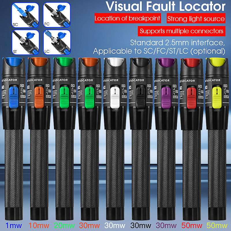
Can a VFL detect faults in both multimode and single-mode fiber installations?
VFL devices work effectively with both multimode and single-mode fiber types, though detection characteristics may vary slightly between fiber types. Multimode fiber typically shows brighter visible indications due to larger core diameter, while single-mode fiber may require closer observation for fault detection. Most modern VFL devices are designed to work optimally with both fiber types and include appropriate connector options for various fiber installation standards.
How does VFL testing integrate with other fiber diagnostic procedures?
VFL testing serves as an ideal first-step diagnostic procedure that can either identify faults immediately or confirm that more advanced testing is required. When VFL testing reveals visible faults, repairs can proceed immediately without additional diagnostic steps. When no visible faults are detected, technicians can proceed with confidence to power meter testing, OTDR analysis, or other diagnostic procedures, knowing that obvious physical faults have been ruled out.
What safety considerations apply when using VFL devices in active fiber networks?
VFL testing should only be performed on inactive fiber circuits to prevent interference with live network traffic and to ensure operator safety when observing visible light output. Most VFL devices include safety features such as automatic shutoff timers and appropriate power levels for safe operation, but technicians must follow proper procedures for network isolation and personal protective equipment use when working with laser-based diagnostic equipment.
Table of Contents
- Immediate Problem Identification Through Visual Light Injection
- Rapid Detection of Multiple Fault Types
- Streamlined Troubleshooting Workflow Integration
- Operational Efficiency in Various Network Environments
- Cost-Effective Diagnostic Investment
-
FAQ
- What range limitations should be considered when using a VFL for fault location?
- Can a VFL detect faults in both multimode and single-mode fiber installations?
- How does VFL testing integrate with other fiber diagnostic procedures?
- What safety considerations apply when using VFL devices in active fiber networks?