
 EN
EN
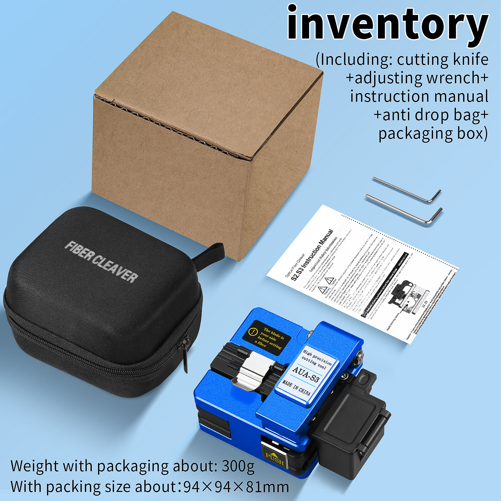
The quality of a fiber cleave stands as the single most critical factor determining the success of low-loss fusion splicing operations in modern optical networks. When fusion splicing technicians prepare optical fibers for joining, the cleave quality directly influences splice loss, mechanical strength, and long-term reliability of the connection. A high-quality cleave creates a perfectly perpendicular end face with minimal surface defects, enabling the fusion splicer to align and fuse fiber cores with precision measured in fractions of a decibel. Understanding what constitutes an exceptional cleave requires examining the geometric, surface quality, and mechanical parameters that professional fiber cleaver tools must deliver consistently across thousands of cleaving operations.
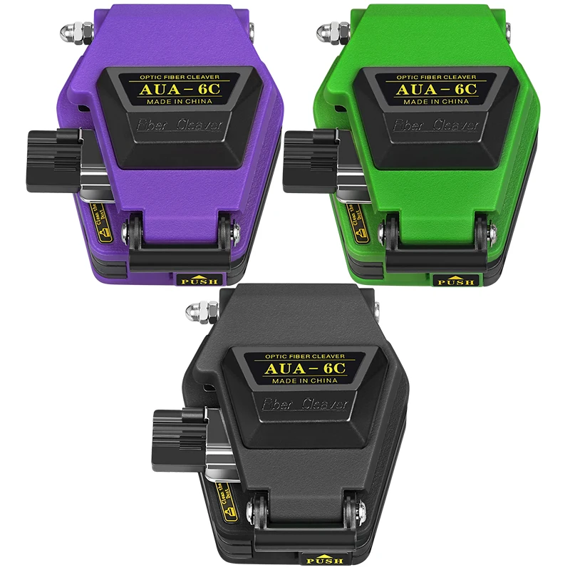
Professional installation teams working on telecommunications infrastructure, data center interconnects, and fiber-to-the-home deployments recognize that even minor variations in cleave quality cascade into measurable performance degradation. A cleave angle deviation of just two degrees can introduce splice losses exceeding 0.5 dB, while surface irregularities create point stresses that compromise mechanical integrity. The precision engineering embedded in advanced fiber cleaver designs addresses these challenges through controlled blade geometry, consistent scoring mechanisms, and tension application systems that propagate fractures through the glass matrix with predictable results. This article examines the specific technical criteria that distinguish superior cleaves from adequate ones, providing insight into how equipment selection and operational technique combine to achieve the low-loss performance demanded by contemporary optical networks.
Geometric Precision Standards for Optimal Cleaves
Cleave Angle Requirements and Measurement
The cleave angle represents the most fundamental geometric parameter defining cleave quality for fusion splicing applications. Industry standards specify that cleave angles must remain within 0.5 degrees of perpendicular to the fiber axis for single-mode fibers, with some advanced applications requiring tolerances as tight as 0.3 degrees. When a fiber cleaver produces end faces outside these specifications, the angular mismatch between fiber cores during splicing introduces Fresnel reflection losses and creates gaps that the fusion arc cannot adequately bridge. Measurement of cleave angles typically occurs through microscopic inspection systems integrated into fusion splicers, which analyze the fiber end face profile before initiating the splice sequence.
Professional fiber cleaver mechanisms achieve consistent angle control through precision blade positioning systems and controlled tension application during the cleaving process. The blade holder assembly in quality tools maintains positioning accuracy within micrometers, ensuring the scoring mark initiates perpendicular to the fiber axis. As tension propagates the initial score into a complete fracture, the fiber cleaver design must prevent any lateral deflection or rotation that would introduce angular deviation. Temperature stability of the cleaver body materials also contributes to angle consistency, as thermal expansion in aluminum or composite housings can shift blade geometry relative to the fiber clamping position across operating temperature ranges encountered in field environments.
End Face Flatness and Surface Topology
Beyond angular precision, the microscopic flatness of the cleaved fiber end face determines how effectively the fusion process can create a homogeneous joint. High-quality cleaves exhibit end face flatness deviations less than 0.5 micrometers across the fiber diameter, measured through interferometric analysis. Surface topology variations create localized gaps during the pre-fusion alignment stage, forcing the fusion splicer to apply higher arc power or extended fusion times to collapse these irregularities. These compensatory measures often introduce excessive heat into the fusion zone, causing bubble formation, core deformation, or dopant migration that elevates splice loss beyond acceptable thresholds for low-loss applications.
The blade material and edge geometry employed in a fiber cleaver directly influence end face flatness outcomes. Diamond or tungsten carbide blades with precisely ground edge profiles initiate controlled fractures that propagate smoothly through the glass matrix without creating step features or lip formations. Blade wear represents a significant concern for maintaining flatness consistency, as even minor edge degradation introduces microchipping that transfers texture patterns onto the cleaved surface. Professional fiber cleaver models incorporate blade rotation or indexing mechanisms that present fresh cutting edges after predetermined cleave counts, ensuring flatness specifications remain within tolerance throughout the blade service life. Regular inspection protocols verify that end face quality has not degraded below acceptable standards before completing critical splice campaigns.
Fiber Tip Geometry and Hackle Formation
The transition zone where the fiber coating ends and the glass cleave begins requires careful examination to identify defects that compromise splice quality. Hackle marks, which appear as fine radial lines extending from the fracture origin point, indicate stress concentrations or irregular fracture propagation during the cleaving process. While some hackle formation is inevitable in glass fracture mechanics, excessive hackle density or depth creates microscopic protrusions that prevent intimate fiber-to-fiber contact during fusion. A precision fiber cleaver manages hackle formation through controlled tension application rates and blade penetration depths that initiate fractures at optimal stress levels within the glass structure.
Fiber tip geometry also encompasses the height and shape of any residual coating material remaining near the cleave plane. Improper coating strip length or ragged coating edges interfere with fiber insertion into the fusion splicer electrodes, potentially causing misalignment or contamination of the cleave surface. Advanced fiber cleaver systems coordinate coating removal and cleaving operations to maintain consistent bare fiber length while preventing coating debris from depositing onto the prepared end face. The integration of coating stripping and cleaving functions within a single tool body eliminates handling steps that could introduce contamination or mechanical damage between preparation stages, contributing to overall cleave quality consistency.
Surface Quality Characteristics for Low-Loss Performance
Contamination Control and Cleanliness Standards
Surface contamination on cleaved fiber end faces represents a primary cause of elevated splice loss and reduced mechanical strength in fusion joints. Particulate matter, coating residues, skin oils, or atmospheric dust particles measuring just a few micrometers in diameter create localized voids or inclusions within the fusion zone that scatter light and concentrate mechanical stress. Professional fiber cleaver operation protocols emphasize contamination prevention through controlled handling procedures, protective blade covers, and immediate transfer of cleaved fibers into fusion splicer holding fixtures. The time interval between cleaving and fusion should be minimized to reduce airborne particle deposition, particularly in dusty field environments where construction activities generate elevated particulate concentrations.
The fiber cleaver mechanism itself must be designed to prevent self-contamination during the cleaving process. Blade assemblies that generate metal particles through wear, or plastic fiber holders that create static charges attracting airborne contaminants, compromise cleave quality regardless of geometric precision. Material selections for fiber contact surfaces prioritize non-shedding compositions with antistatic properties that neither generate nor attract particulate matter. Regular cleaning protocols for fiber cleaver components remove accumulated debris from blade assemblies, fiber guides, and clamping surfaces using lint-free materials and approved solvents that evaporate completely without leaving residues. Documentation of cleaning activities ensures traceability when investigating anomalous splice loss patterns across installation projects.
Microscopic Defect Identification and Classification
Detailed inspection of cleaved end faces reveals various defect types that impact fusion splice performance differently. Chips along the fiber perimeter create stress concentration points that reduce tensile strength, while surface scratches parallel to the fiber axis indicate blade edge defects or contaminated fiber holders. Lips or hooks at the cleave edge result from excessive blade penetration or improper tension application timing, preventing proper fiber seating in the fusion splicer electrode grooves. Each defect category traces back to specific aspects of fiber cleaver design or operational technique, enabling systematic troubleshooting when quality metrics decline below specification targets.
Classification systems for cleave defects provide standardized frameworks for quality assessment and process control. The most widely adopted standards categorize defects by severity level, with Class A cleaves exhibiting no visible defects under 400x magnification, Class B showing minor imperfections that do not significantly impact splice performance, and Class C displaying defects requiring fiber re-cleaving before attempting fusion. Automated inspection systems integrated into modern fusion splicers perform this classification instantly, rejecting substandard cleaves before fusion attempts that would waste time and consumables. Training programs for fiber cleaver operators emphasize defect recognition skills, enabling field technicians to diagnose equipment issues or technique errors that generate recurring defect patterns across multiple cleave attempts.
Core Concentricity and Alignment Implications
While not strictly a cleave quality parameter, the relationship between the cleaved end face and the fiber core position significantly influences fusion splice loss outcomes. Manufacturing tolerances in optical fiber production create variations in core-to-cladding concentricity, with the core positioned slightly off-center within the glass cladding diameter. When a fiber cleaver produces angled or non-flat end faces, these geometric deviations compound with core eccentricity to create alignment challenges that the fusion splicer must compensate through profile alignment systems. The cumulative effect of these factors becomes particularly significant in long-haul transmission systems where splice loss budgets allow minimal margin for geometric imperfections.
High-precision fiber cleaver designs minimize their contribution to alignment errors through symmetric clamping systems that center fibers accurately within the cleaving mechanism. Blade holders positioned along the fiber centerline ensure scoring occurs at the geometric center of the cladding diameter, preventing eccentric fracture initiation points that could propagate asymmetrically. Quality verification procedures include measurement of cleave-to-cleave consistency across multiple samples, with statistical analysis identifying systematic biases in end face geometry that indicate misalignment within the fiber cleaver mechanism. Calibration protocols adjust blade positioning or fiber holder alignment to null out these systematic errors, ensuring the cleaver contributes minimal uncertainty to the overall splice loss budget.
Mechanical Characteristics Affecting Splice Strength
Fracture Propagation Control and Stress Distribution
The microscopic process of fracture propagation through the glass fiber structure during cleaving determines both the geometric quality of the end face and the residual stress distribution within the cleaved tip region. Controlled fracture propagation initiates from the blade score mark and travels across the fiber diameter along a plane perpendicular to the fiber axis, creating the desired flat end face. Uncontrolled propagation results from excessive blade penetration depth, inadequate tension application, or blade edge defects that introduce multiple fracture initiation sites competing during the cleaving process. These competing fractures create irregular end face topologies with stress concentrations that reduce the mechanical strength of completed fusion splices.
Advanced fiber cleaver mechanisms incorporate tension control systems that apply precise pulling forces to the fiber during cleaving, ensuring fracture propagation occurs at optimal velocity through the glass matrix. Too-rapid fracture propagation generates excessive hackle and surface roughness, while too-slow propagation allows crack deflection that creates angled end faces. The relationship between blade penetration depth and applied tension must be calibrated for different fiber types, as variations in glass composition, dopant concentrations, and cladding diameter all influence the fracture mechanics of the cleaving process. Professional fiber cleaver models offer adjustable tension settings or automatic adaptation based on fiber type selection, optimizing fracture control across the range of fiber specifications encountered in network installation projects.
Residual Stress Patterns and Long-Term Reliability
The cleaving process introduces residual stress patterns into the fiber tip region that persist through the fusion splicing operation and influence the long-term mechanical reliability of the completed joint. Tensile stresses concentrated near the cleave plane can initiate crack propagation under mechanical loading or thermal cycling, leading to delayed splice failures months or years after installation. High-quality cleaves minimize residual stress concentrations through controlled fracture propagation and appropriate blade geometry that distributes stress uniformly across the end face during the scoring and breaking sequence. Stress analysis using polarized light microscopy reveals these residual stress patterns, enabling correlation between fiber cleaver operating parameters and long-term splice reliability outcomes.
The fusion process itself partially relieves residual stresses introduced during cleaving through thermal annealing of the fiber tip region at temperatures approaching the glass softening point. However, excessive residual stress from poor cleave quality may not be fully relieved during standard fusion cycles, requiring extended annealing times that reduce splicing throughput. Some fusion splicer models incorporate stress analysis routines that measure residual stress levels through optical retardation measurements, rejecting cleaves with excessive stress concentrations before attempting fusion. This quality gate prevents the creation of mechanically weak splices that would fail prematurely under field operating conditions, particularly in installations subject to vibration, temperature extremes, or tensile loading during cable pulling operations.
Edge Chip Prevention and Perimeter Integrity
Microscopic chips along the fiber perimeter at the cleave plane represent critical defects that dramatically reduce splice tensile strength even when the central end face region exhibits excellent geometric quality. These edge chips typically originate from lateral blade movement during scoring, excessive blade penetration that crushes rather than scores the glass surface, or contamination particles trapped between the blade and fiber during the cleaving stroke. A single perimeter chip measuring just tens of micrometers in size can reduce splice strength by fifty percent or more, as stress concentrations at the chip location initiate catastrophic fracture propagation under tensile loading conditions.
Prevention of edge chip formation requires fiber cleaver designs that stabilize both the fiber and blade during the scoring operation. Precision fiber holders with V-groove or cylindrical clamping surfaces prevent fiber rotation or lateral movement as the blade contacts the glass surface. Blade guidance systems maintain perpendicular approach angles and prevent blade deflection during the scoring stroke, ensuring consistent penetration depth around the fiber circumference. Quality fiber cleaver models incorporate blade wear monitoring systems that track the number of cleaves performed and alert operators when blade replacement or rotation is required to maintain edge quality specifications. Post-cleave inspection protocols specifically examine the fiber perimeter under magnification, documenting edge integrity as part of quality assurance procedures for critical splice installations.
Equipment Design Features Supporting Quality Cleaves
Blade Technology and Edge Retention
The blade assembly represents the core technology component determining cleave quality consistency in fiber cleaver equipment. Modern blades employ diamond or tungsten carbide materials with precisely controlled edge geometries optimized for glass fracture initiation. Diamond blades offer superior edge retention, maintaining scoring consistency across tens of thousands of cleaves before requiring rotation or replacement. The edge profile geometry, including rake angle, included angle, and edge radius, must be optimized for the specific glass compositions encountered in telecommunications fibers. Single-mode fibers with germanosilicate core compositions require different blade geometries compared to multimode fibers with higher numerical apertures and different dopant systems.
Blade mounting systems in professional fiber cleaver designs provide micrometer-level positioning adjustment and rigid support during the cleaving operation. Blade holders fabricated from temperature-stable materials prevent thermal expansion effects that would alter blade-to-fiber geometry across the operating temperature range. Some advanced fiber cleaver models incorporate multiple blade positions within a rotating holder, allowing operators to index to fresh blade edges when cleave quality monitoring indicates performance degradation. This blade rotation capability extends equipment operational life and ensures consistent cleave quality throughout extended splice campaigns in field environments where blade replacement would require work interruption and recalibration procedures.
Fiber Positioning and Clamping Mechanisms
Accurate fiber positioning within the fiber cleaver mechanism is essential for achieving consistent cleave geometry across repeated operations. Professional tools employ precision-ground fiber guides that establish repeatable reference positions for fiber insertion, ensuring the blade scores the fiber at the intended location relative to the coating strip endpoint. Clamping mechanisms must secure the fiber firmly without introducing deformation or stress concentrations that would influence fracture propagation during the cleaving process. Rubber or elastomer clamping pads distribute clamping forces uniformly around the fiber circumference, preventing localized compression that could create preferential fracture paths.
The geometry of fiber positioning elements must accommodate dimensional variations across different fiber types while maintaining positioning accuracy. Standard single-mode fibers with 125-micrometer cladding diameter require different holder dimensions compared to specialty fibers with 80-micrometer or reduced cladding designs. Adjustable fiber guides in versatile fiber cleaver models enable accommodation of these dimensional ranges without compromising positioning precision. Fiber insertion depth control mechanisms ensure consistent bare fiber length extension beyond the clamping point, establishing the proper relationship between coating edge, blade position, and subsequent cleave location. This dimensional control becomes particularly critical in ribbon fiber cleaving applications where multiple fibers must be cleaved simultaneously with matched end face positions for mass fusion splicing operations.
Tension Application and Fracture Control Systems
Controlled application of tensile stress to the scored fiber initiates and guides the fracture propagation process that completes the cleave. Simple fiber cleaver designs rely on manual tension application through lever mechanisms or weighted pendulums, while advanced models incorporate spring-loaded or pneumatic systems that deliver precisely calibrated tension forces. The tension application rate, peak force magnitude, and duration of force application all influence fracture propagation velocity and end face quality outcomes. Optimal tension parameters vary with fiber type, coating materials, and environmental conditions including temperature and humidity that affect glass fracture mechanics.
Sophisticated fiber cleaver mechanisms coordinate blade retraction timing with tension application to ensure the fracture initiates only after the blade has fully withdrawn from contact with the fiber surface. This sequencing prevents blade interference with the propagating fracture front that could deflect the crack path and create angled end faces. Acoustic or optical sensors in research-grade fiber cleaver designs monitor fracture propagation in real-time, providing feedback for adaptive tension control that optimizes cleave quality across varying fiber specifications. While such advanced features remain primarily in laboratory instruments, the underlying principles inform the design of production fiber cleaver tools where manual technique and operator skill partially compensate for the absence of automated control systems.
Operational Techniques for Consistent Results
Fiber Preparation and Handling Protocols
Proper fiber preparation procedures before insertion into the fiber cleaver significantly influence cleave quality outcomes. Coating removal must be performed with appropriate stripping tools that cleanly remove buffer and coating layers without scoring or damaging the underlying glass cladding. Mechanical strippers sized correctly for the specific fiber coating system prevent excessive stripping force that creates microcracks in the glass surface. Chemical strippers offer gentler coating removal but require thorough cleaning to eliminate solvent residues that could contaminate the cleave surface or interfere with fracture propagation during the cleaving operation.
Handling of stripped fiber sections demands careful technique to prevent contamination or mechanical damage before cleaving. Operators should avoid touching the bare glass surface with fingers, tools, or other surfaces that could transfer oils, particles, or moisture onto the fiber. Immediate transfer of stripped fibers into the fiber cleaver mechanism minimizes airborne contamination exposure in field environments. When cleaving cannot be performed immediately after stripping, temporary storage in protective containers or holder fixtures prevents contact with contaminated surfaces. Training programs emphasize these handling protocols, as field observations consistently demonstrate that contamination-related cleave quality issues trace to improper fiber handling rather than equipment deficiencies in the majority of troubleshooting investigations.
Environmental Condition Management
Environmental factors including temperature, humidity, and atmospheric cleanliness significantly impact fiber cleaver performance and cleave quality consistency. Temperature extremes affect both the fiber cleaver mechanism through thermal expansion effects and the glass fiber itself through changes in fracture mechanics properties. Manufacturers specify operating temperature ranges for fiber cleaver equipment, typically spanning from freezing to moderate heat levels encountered in shaded field locations. Operation outside these temperature specifications can result in blade positioning errors, clamping mechanism malfunction, or altered fracture propagation characteristics that degrade cleave quality below acceptable standards.
Humidity influences static charge accumulation on fiber surfaces and can promote condensation in humid conditions or during temperature transitions. Static charges attract airborne particles onto cleaved end faces, while condensation introduces moisture contamination that interferes with fusion splicing operations. Professional installation practices include environmental monitoring and control measures such as portable climate-controlled enclosures for splice operations in extreme conditions. Wind protection prevents airborne debris from contaminating work surfaces and cleaved fiber end faces during outdoor installations. Recognition of environmental limitations and implementation of appropriate control measures ensures consistent fiber cleaver performance across the diverse conditions encountered during network deployment projects.
Quality Verification and Process Monitoring
Systematic quality verification procedures provide feedback loops that maintain fiber cleaver performance within specification over extended operational periods. Visual inspection of cleaved end faces under magnification represents the most fundamental quality check, enabling detection of gross defects before attempting fusion splicing. Portable microscopes with calibrated measurement reticles allow field verification of cleave angle and end face quality, though full characterization requires the imaging systems integrated into fusion splicers. Statistical monitoring of cleave quality metrics across splice campaigns identifies trends indicating blade wear, mechanism misalignment, or technique issues requiring corrective action before quality degradation affects splice performance.
Process control documentation captures cleave quality data, equipment maintenance activities, and environmental conditions for each splice campaign. This documentation enables root cause analysis when splice loss measurements exceed specification limits, distinguishing fiber cleaver issues from fusion splicer problems or fiber quality variations. Correlation analysis between cleave quality metrics and completed splice loss measurements validates that fiber cleaver performance remains adequate for the specific loss budget requirements of each project. Proactive quality monitoring and equipment maintenance based on documented performance trends prevents the accumulation of minor degradation factors that could eventually compromise splice quality during critical installation phases where rework would create unacceptable schedule delays.
FAQ
What cleave angle tolerance is required for low-loss single-mode fiber splicing?
Industry standards specify cleave angles within 0.5 degrees of perpendicular to the fiber axis for standard single-mode fusion splicing applications. More stringent requirements exist for ultra-low-loss splicing in long-haul transmission systems, where cleave angle tolerances tighten to 0.3 degrees or less. Modern fusion splicers with profile alignment systems can partially compensate for cleave angle deviations through sophisticated core alignment algorithms, but maintaining tight angle tolerances at the fiber cleaver stage minimizes splice loss and improves process reliability. Field-deployable fiber cleaver equipment capable of consistently meeting these specifications typically incorporates precision blade positioning mechanisms and controlled tension application systems that ensure perpendicular fracture propagation through the glass fiber structure.
How many cleaves can be performed before blade replacement becomes necessary?
Blade life in professional fiber cleaver equipment ranges from several thousand to over thirty thousand cleaves depending on blade material, edge geometry, and operating conditions. Diamond blades with optimized edge profiles typically provide fifteen to thirty thousand cleaves before rotation or replacement, while tungsten carbide blades may require more frequent service. Actual blade life varies significantly based on fiber types cleaved, with specialty fibers or contaminated work environments accelerating wear rates. Most manufacturers recommend monitoring cleave quality through periodic inspection rather than relying solely on cleave count, as operating conditions influence degradation rates. Quality metrics including increased cleave angle deviation, surface roughness, or edge chip frequency indicate blade replacement needs before cleave quality falls below acceptable standards for low-loss splicing applications.
Can environmental factors affect fiber cleaver performance in field installations?
Environmental conditions significantly impact fiber cleaver performance and cleave quality consistency during field deployment operations. Temperature extremes cause thermal expansion in cleaver mechanism components, potentially shifting blade alignment or affecting clamping mechanism function. High humidity promotes static charge accumulation and condensation on fiber surfaces, increasing contamination risk. Dusty or windy conditions introduce airborne particles that contaminate cleaved end faces or accumulate within cleaver mechanisms. Professional installation practices address these challenges through environmental controls such as portable work enclosures, climate monitoring, and adjusted operational protocols during extreme conditions. Equipment specifications define acceptable operating temperature and humidity ranges, with operation outside these limits risking degraded cleave quality that increases splice loss or reduces mechanical strength. Proper environmental management ensures fiber cleaver performance remains within specification across diverse field conditions encountered during telecommunications network installation projects.
What inspection methods verify cleave quality before fusion splicing?
Cleave quality verification employs several inspection methods ranging from simple visual examination to sophisticated automated analysis. Portable fiber microscopes with 200x to 400x magnification enable field inspection of end face geometry, revealing gross defects such as angled cleaves, chips, or contamination. More detailed characterization requires the automated inspection systems integrated into modern fusion splicers, which capture high-resolution images of fiber end faces and perform automated measurements of cleave angle, end face flatness, and defect classification. These systems provide pass/fail determinations based on programmable quality thresholds before initiating fusion sequences. Laboratory characterization methods including interferometry and scanning electron microscopy reveal microscopic surface features and residual stress patterns, though these techniques remain primarily research tools rather than routine quality control methods. Field installation procedures emphasize the splicer-integrated inspection capability as the practical quality gate ensuring only acceptable cleaves proceed to fusion, preventing wasted fusion cycles and ensuring low-loss splice performance.
Table of Contents
- Geometric Precision Standards for Optimal Cleaves
- Surface Quality Characteristics for Low-Loss Performance
- Mechanical Characteristics Affecting Splice Strength
- Equipment Design Features Supporting Quality Cleaves
- Operational Techniques for Consistent Results
-
FAQ
- What cleave angle tolerance is required for low-loss single-mode fiber splicing?
- How many cleaves can be performed before blade replacement becomes necessary?
- Can environmental factors affect fiber cleaver performance in field installations?
- What inspection methods verify cleave quality before fusion splicing?