
 EN
EN
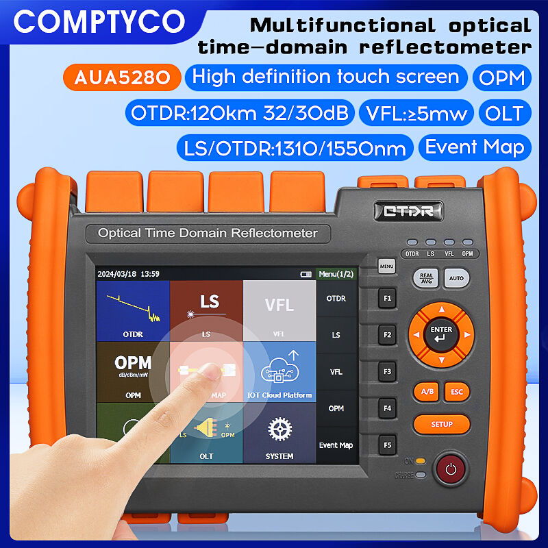
Fiber optic networks depend heavily on the testing methodologies applied during installation, maintenance, and troubleshooting phases. The deployment environment—whether underground or aerial—introduces distinct challenges that directly affect how technicians use diagnostic equipment to verify cable integrity. An optical time domain reflectometer serves as the primary tool for measuring attenuation, locating faults, and characterizing splice quality, yet the strategic approach to testing must adapt based on whether cables run beneath the surface or suspend overhead. Understanding these differences ensures accurate diagnostics, reduces downtime, and optimizes resource allocation across diverse network topologies.
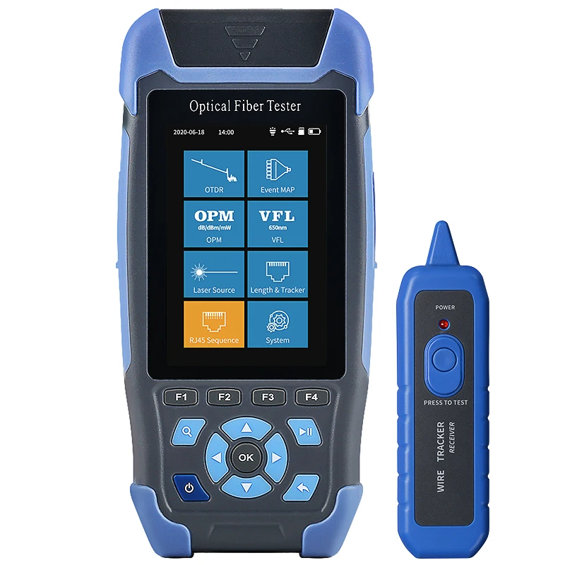
Underground and aerial cable installations present contrasting physical conditions, environmental stresses, and accessibility constraints that influence every aspect of optical testing. Buried fiber optic cables face soil pressure, moisture infiltration, and mechanical disturbances from excavation activities, while aerial cables endure wind-induced tension, temperature fluctuations, and potential damage from wildlife or weather events. These environmental factors shape how technicians configure their optical time domain reflectometer settings, interpret trace data, and prioritize testing intervals. The comparative analysis of these two deployment strategies reveals critical operational insights that empower network operators to implement proactive maintenance protocols and achieve superior service reliability.
Environmental Factors Influencing Testing Protocols
Underground Cable Testing Considerations
Underground fiber optic installations require specialized testing strategies due to the unique environmental conditions surrounding buried cables. Soil moisture content significantly affects the thermal stability of fiber connections, causing seasonal variations in attenuation measurements captured by an optical time domain reflectometer. Technicians must account for these fluctuations when establishing baseline performance metrics and identifying genuine fault conditions versus environmentally induced signal variations. The compression forces exerted by overlying soil layers can introduce microbending losses that gradually degrade signal quality over time, necessitating more frequent verification tests compared to aerial deployments.
The access limitations inherent to underground cable systems directly impact testing efficiency and fault localization accuracy. When an optical time domain reflectometer detects an anomaly in a buried cable segment, technicians face the challenge of pinpointing the exact physical location for excavation without visual reference points. This demands precise distance measurements and correlation with installation records that document splice enclosure positions, directional bores, and conduit pathways. Temperature gradients between surface conditions and burial depth further complicate measurements, as the refractive index of optical fiber changes with thermal variation, potentially introducing distance calculation errors that must be compensated through proper device calibration.
Aerial Cable Environmental Challenges
Aerial fiber optic cables suspended between utility poles encounter mechanical stresses absent in underground installations, requiring adjusted testing protocols that account for tension-induced attenuation variations. Wind loading creates dynamic fiber strain conditions that an optical time domain reflectometer must measure under multiple environmental states to establish accurate performance baselines. The diurnal temperature cycle causes expansion and contraction of both the supporting messenger wire and the fiber optic cable itself, introducing measurable changes in optical path length that technicians must distinguish from actual network degradation. Aerial cables also experience greater exposure to lightning-induced surges and ice accumulation during winter months, both of which can cause sudden catastrophic failures or gradual performance deterioration.
The accessibility advantages of aerial deployments allow for visual inspection coordination with optical testing data, creating opportunities for more comprehensive diagnostic workflows. Technicians can directly observe physical damage indicators such as abraded cable jackets, sagging spans, or loose hardware while simultaneously analyzing the optical signature captured by their testing equipment. This synergy between visual assessment and optical time domain reflectometer measurements enables faster fault correlation and more confident repair decisions. However, the elevated working environment introduces safety considerations that affect testing scheduling, as high-wind conditions or precipitation may prevent both optical measurements and physical access until weather conditions improve, potentially extending network outage durations.
Measurement Configuration and Parameter Optimization
Pulse Width Selection Based on Cable Length
The configuration of an optical time domain reflectometer begins with selecting appropriate pulse width settings that balance spatial resolution against signal-to-noise ratio requirements. Underground cable installations often incorporate longer continuous runs between access points, sometimes exceeding several kilometers without intermediate splice enclosures. These extended lengths demand wider pulse widths to generate sufficient backscattered light for clear trace visualization, typically ranging from one to ten microseconds depending on total span distance. The trade-off involves reduced ability to distinguish closely spaced events such as connector pairs or fusion splices located within short distances of each other, which may prove acceptable when underground vaults space connection points at greater intervals.
Aerial cable networks frequently employ shorter span lengths dictated by pole spacing, typically ranging from forty to one hundred fifty meters between support points. This segmented topology benefits from narrower pulse width configurations that provide superior spatial resolution for identifying individual span characteristics and locating faults with precision sufficient to direct bucket truck positioning. An optical time domain reflectometer configured with ten to thirty nanosecond pulse widths can distinguish events separated by as little as one meter, enabling technicians to differentiate between a splice at a pole location and a bend-induced loss occurring within the adjacent span. The enhanced resolution proves particularly valuable when analyzing aerial cable sections traversing urban environments where numerous poles and service drops create complex trace signatures requiring careful interpretation.
Dynamic Range Requirements for Different Installations
The dynamic range specification of an optical time domain reflectometer determines the maximum cable length that can be effectively characterized without signal amplification or intermediate testing points. Underground installations serving metropolitan area networks or long-haul telecommunications routes may extend twenty to sixty kilometers between terminal equipment locations, demanding instruments with dynamic range capabilities exceeding thirty-five decibels to capture usable traces across entire cable sections. Insufficient dynamic range forces technicians to establish multiple testing positions along the cable route, increasing labor costs and potentially missing faults located in segments between test access points.
Aerial cable deployments typically involve shorter overall distances, particularly in distribution networks serving residential or commercial areas where cable routes rarely exceed five to fifteen kilometers between central offices and remote terminals. These applications permit the use of optical time domain reflectometer models with more modest dynamic range specifications, potentially reducing equipment investment costs while still achieving comprehensive network characterization. However, aerial networks supporting wireless backhaul applications or interconnecting geographically dispersed facilities may approach or exceed the length requirements of underground systems, necessitating similar high-performance instrumentation. The selection process must consider not only current network extent but also planned expansion scenarios that could extend cable runs beyond the capabilities of lower-specification test equipment.
Fault Detection and Localization Strategies
Identifying Underground Cable Failures
Underground fiber optic cable failures typically manifest as either catastrophic breaks resulting in complete signal loss or gradual degradation caused by progressive mechanical stress or moisture infiltration. An optical time domain reflectometer identifies catastrophic failures through the appearance of a strong reflective event followed by immediate noise floor, indicating fiber discontinuity at the fault location. The distance measurement provided by the instrument guides excavation crews to the approximate failure point, though additional techniques such as acoustic tone tracing or electromagnetic cable locating may supplement optical measurements to confirm the precise lateral position before digging commences. Third-party excavation damage represents the most common cause of underground cable failures, often producing clean breaks with minimal fiber end-face contamination that simplifies subsequent repair procedures.
Progressive underground cable degradation presents more subtle diagnostic challenges requiring trend analysis of repeated optical time domain reflectometer measurements over extended monitoring periods. Gradual increases in splice loss or bend-induced attenuation may signal developing problems such as splice enclosure water infiltration, soil settlement causing cable compression, or inadequate slack management allowing tension transfer to fiber strands. Technicians establish baseline trace signatures immediately following installation and compare subsequent measurements against these references to detect performance drift before service-affecting failures occur. The analysis process involves quantifying loss values at known splice locations and comparing measurements taken from both cable directions to isolate asymmetric loss patterns that suggest specific failure mechanisms requiring preventive intervention.
Locating Aerial Cable Damage
Aerial fiber optic cable faults often result from weather-related events, wildlife interaction, or vehicular impact with supporting infrastructure, creating damage patterns distinctly different from underground failure modes. An optical time domain reflectometer trace showing sudden high-loss events or fiber breaks can be correlated with visual pole-to-pole inspection to identify physical damage indicators such as bullet holes, bird pecking, or abrasion from contact with tree branches. The elevated position of aerial cables facilitates direct observation of the failure location once the optical measurement provides distance information, significantly reducing the diagnostic time compared to buried cable scenarios where excavation must precede visual confirmation.
Ice storm damage to aerial cable plants produces characteristic optical signatures involving multiple high-loss events or breaks distributed across extended cable sections as accumulated ice weight exceeds mechanical design limits. Optical time domain reflectometer testing following severe weather events reveals the extent of damage across the affected network area, enabling repair crews to prioritize restoration efforts based on the number of affected customers and the severity of individual cable failures. The testing strategy involves systematic measurement of all cable routes within the impacted geographic region, documenting fault locations and loss magnitudes to optimize material procurement and crew deployment. This comprehensive assessment approach minimizes repeated truck rolls and ensures efficient allocation of restoration resources during large-scale outage events affecting multiple aerial cable segments simultaneously.
Testing Frequency and Maintenance Scheduling
Proactive Underground Cable Monitoring
Underground fiber optic networks benefit from scheduled optical time domain reflectometer testing intervals that detect gradual performance degradation before service interruptions occur. Industry best practices recommend annual baseline measurements for stable underground installations, with increased frequency for cables in areas prone to ground movement, construction activity, or documented previous failures. The accumulated test data creates a historical performance database enabling trend analysis that identifies slowly developing problems such as splice degradation, connector contamination, or fiber stress concentration at cable bends. Proactive testing programs reduce emergency repair costs by allowing scheduled maintenance during normal business hours rather than expensive after-hours or weekend emergency responses.
Critical underground cable routes supporting high-value services or serving large customer populations warrant more aggressive testing schedules, potentially including quarterly or even monthly optical time domain reflectometer measurements depending on service level agreement requirements and network reliability objectives. The testing protocol should encompass bidirectional measurements to capture asymmetric loss conditions that might indicate developing connector issues or directional splice problems. Automated testing systems incorporating remotely accessible optical switches and permanently installed monitoring equipment enable continuous or daily measurements without dispatching field technicians, though the capital investment required for such infrastructure typically limits deployment to only the most critical network segments where downtime costs justify the expenditure.
Aerial Cable Testing Protocols
Aerial fiber optic cable testing schedules typically incorporate more frequent measurements compared to underground installations due to the increased exposure to environmental stresses and mechanical disturbances. Semi-annual optical time domain reflectometer testing represents a common baseline approach for aerial plant, with additional measurements following severe weather events that may cause cable damage through ice loading, wind stress, or lightning strikes. The testing workflow often combines optical measurements with visual pole-line inspections, allowing technicians to correlate optical performance data with observed physical conditions such as sagging cables, damaged hardware, or vegetation encroachment requiring clearance.
Aerial cables traversing areas with frequent vehicle strikes, such as cables crossing roadways at low clearance points, require enhanced monitoring attention with testing intervals potentially shortened to quarterly measurements. The optical time domain reflectometer data collected during these assessments documents any impact-related damage that may not immediately cause service failure but creates stress concentration points likely to develop into future breaks. Similarly, aerial cable sections exposed to chronic tree contact or known wildlife activity benefit from increased testing frequency to detect abraded cable jackets or pecking damage before fiber strands become compromised. The cumulative testing investment proves cost-effective by preventing catastrophic failures that would require emergency restoration and potential service credit obligations to affected customers.
Data Analysis and Interpretation Techniques
Underground Cable Trace Characteristics
Analyzing optical time domain reflectometer traces from underground cable installations requires understanding the typical signature patterns associated with buried fiber infrastructure. The relatively uniform temperature and protection from mechanical disturbance generally produces clean traces with well-defined splice events and gradual attenuation slopes between connection points. Deviations from expected patterns warrant investigation, such as unexplained loss increases suggesting moisture infiltration into splice enclosures or irregular trace sections indicating possible fiber stress from soil settlement. Technicians compare current measurements against installation baseline data to quantify any performance changes, with loss increases exceeding point-two decibels at splice locations triggering further diagnostic investigation.
The burial environment introduces specific measurement considerations that affect optical time domain reflectometer data interpretation. Temperature-dependent refractive index variations can cause apparent distance measurement shifts between summer and winter testing sessions, typically amounting to several meters over multi-kilometer cable spans. Experienced technicians recognize these seasonal variations as normal thermal effects rather than indicators of cable movement or fault conditions. Additionally, the permanent nature of underground installations means that trace signatures remain relatively stable over time, making anomaly detection straightforward through simple overlay comparison of sequential test results. Any sudden appearance of new reflective events or loss increases demands immediate investigation as underground cables rarely experience gradual degradation without specific causal factors such as water intrusion or mechanical stress.
Aerial Cable Signature Analysis
Optical time domain reflectometer traces from aerial cable systems often exhibit more variability compared to underground installations due to environmental exposure and mechanical stress factors. Wind-induced fiber movement can introduce minor trace variations between measurements taken under different weather conditions, requiring technicians to recognize normal variability ranges versus genuine performance degradation. The pole-to-pole span architecture creates regular spacing of splice events corresponding to connection points at support structures, producing characteristic periodic patterns that aid in correlating optical measurements with physical infrastructure locations. Deviations from expected splice spacing may indicate measurement errors, incorrect fiber identification, or documentation discrepancies requiring field verification.
Temperature effects on aerial cables prove more pronounced than underground counterparts due to direct solar exposure and ambient air temperature variations throughout daily and seasonal cycles. An optical time domain reflectometer measurement taken during midday summer heat may show different loss characteristics compared to early morning winter testing of the same cable section, purely due to thermal effects on fiber attenuation coefficients and mechanical tension. Professional testing protocols account for these variables by standardizing measurement conditions or documenting environmental parameters alongside test data for proper interpretation. The analysis process also considers the cumulative effects of repeated thermal cycling and mechanical stress that gradually degrade aerial cable performance over multi-year service periods, distinguishing normal aging patterns from accelerated degradation requiring preventive intervention.
FAQ
What is the primary difference in testing underground versus aerial fiber optic cables with an optical time domain reflectometer?
The primary difference involves environmental exposure and accessibility constraints that shape testing strategies. Underground cables require testing protocols that account for moisture effects, soil pressure, and limited access for fault localization, while aerial cables demand consideration of mechanical tension variations, temperature cycling, and the ability to correlate optical measurements with visual inspection. Underground installations typically feature longer continuous cable runs requiring wider pulse widths and higher dynamic range capabilities, whereas aerial deployments often involve shorter segments with more frequent splice points benefiting from narrower pulses providing superior spatial resolution. Additionally, fault localization in underground systems depends entirely on accurate distance measurements from the optical time domain reflectometer, while aerial cable troubleshooting combines optical data with direct visual observation to expedite repair processes.
How do environmental conditions affect optical time domain reflectometer measurement accuracy in different deployment scenarios?
Environmental conditions significantly influence measurement accuracy through multiple mechanisms affecting both the fiber optic cable and the optical time domain reflectometer instrumentation. Temperature variations alter the refractive index of optical fiber, causing apparent distance measurement changes that can introduce several meters of error over long cable spans when comparing measurements taken under different thermal conditions. Underground cables experience relatively stable temperatures with gradual seasonal variation, while aerial cables undergo rapid temperature swings due to direct solar heating and ambient air exposure, requiring technicians to document environmental conditions alongside test data for proper interpretation. Moisture infiltration in underground splice enclosures can progressively increase splice loss over time, creating gradual trace signature changes that trend analysis reveals. Aerial cable mechanical tension from wind loading or ice accumulation introduces temporary attenuation variations that must be distinguished from permanent degradation when analyzing optical time domain reflectometer traces.
What testing frequency should network operators implement for underground and aerial fiber optic infrastructure?
Testing frequency recommendations depend on cable criticality, environmental risk factors, and historical performance patterns specific to each network segment. Underground cables in stable soil conditions with minimal construction activity typically warrant annual optical time domain reflectometer baseline measurements, while routes in areas prone to excavation damage or ground movement benefit from semi-annual or quarterly testing. Aerial cable infrastructure generally requires more frequent monitoring, with semi-annual testing representing a common baseline approach and additional measurements following severe weather events such as ice storms or high winds. Critical network segments supporting high-value services or large customer populations justify increased testing frequency regardless of deployment method, potentially including monthly measurements or continuous automated monitoring for the most essential routes. The testing schedule should also incorporate event-driven measurements triggered by service degradation reports, nearby construction notifications, or observed physical damage during routine inspections.
Can the same optical time domain reflectometer effectively test both underground and aerial cable installations?
A single optical time domain reflectometer with appropriate specification ranges can effectively test both underground and aerial fiber optic installations, though the optimal device characteristics differ between deployment scenarios. The instrument must provide sufficient dynamic range to characterize the longest anticipated cable runs, which typically occur in underground applications, ensuring the device remains suitable for both environment types. Adjustable pulse width settings allow technicians to optimize spatial resolution for shorter aerial cable spans while maintaining the signal strength necessary for extended underground routes. Modern multifunction optical time domain reflectometer models incorporate automated measurement modes and adaptive configuration algorithms that simplify the testing process across diverse installation types. However, organizations operating networks with distinctly different underground and aerial cable characteristics might optimize their testing capabilities by maintaining specialized equipment tailored to each environment, particularly when underground routes exceed the distance capabilities of compact instruments adequate for aerial distribution networks.
Table of Contents
- Environmental Factors Influencing Testing Protocols
- Measurement Configuration and Parameter Optimization
- Fault Detection and Localization Strategies
- Testing Frequency and Maintenance Scheduling
- Data Analysis and Interpretation Techniques
-
FAQ
- What is the primary difference in testing underground versus aerial fiber optic cables with an optical time domain reflectometer?
- How do environmental conditions affect optical time domain reflectometer measurement accuracy in different deployment scenarios?
- What testing frequency should network operators implement for underground and aerial fiber optic infrastructure?
- Can the same optical time domain reflectometer effectively test both underground and aerial cable installations?