
 EN

An optical time domain reflectometer, commonly known as an otdr, is one of the most valuable instruments in fiber optic network maintenance and troubleshooting. For telecommunications professionals and network operators, the otdr serves as a critical diagnostic tool that reveals the health status of fiber optic cables, identifies potential faults before they cause outages, and provides detailed insights into transmission line performance. Understanding how to use an otdr effectively transforms your network management approach from reactive problem-solving to proactive health monitoring. Periodic otdr testing enables you to catch signal degradation, connector issues, and splice defects early, ensuring your network infrastructure maintains peak reliability and performance.
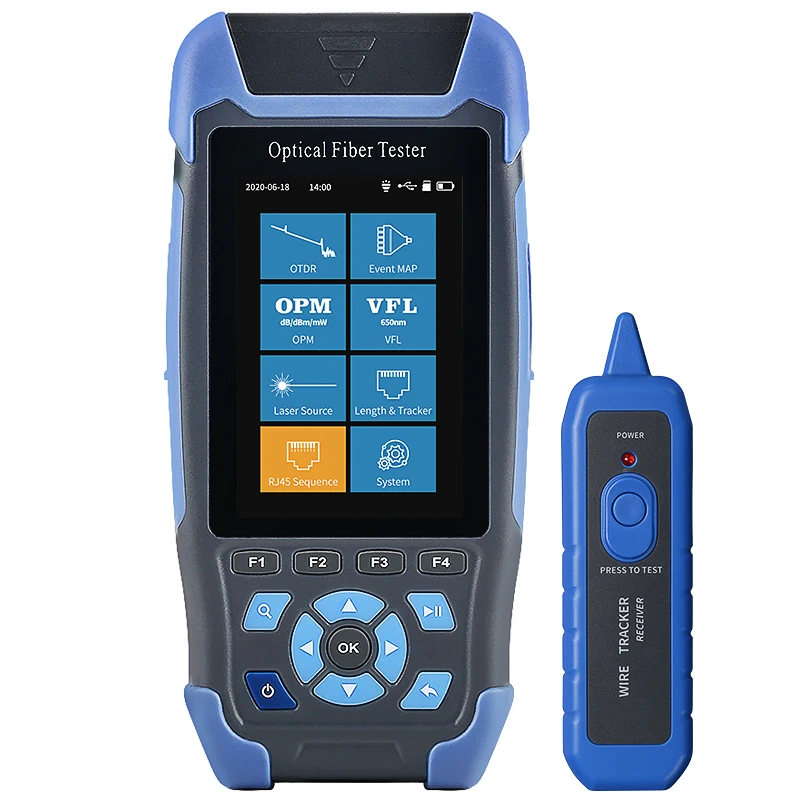
The otdr works by sending short pulses of light down the fiber optic cable and measuring the reflected signals that bounce back from various points along the route. This fundamental operating principle allows the otdr to generate a comprehensive trace showing the distance, magnitude, and nature of every reflection, loss point, and discontinuity within your cable system. By mastering otdr operation and interpretation, network teams can establish a continuous health monitoring program that identifies emerging issues, verifies system upgrades, and documents baseline performance for compliance and troubleshooting reference.
Understanding OTDR Fundamentals and Measurement Principles
How the OTDR Generates Diagnostic Data
The otdr operates through a time-of-flight measurement methodology that calculates distance by analyzing light pulse travel time and reflection characteristics. When you launch a pulse into the fiber, the otdr measures the elapsed time until reflected light returns to the instrument. By correlating travel time with the known speed of light in fiber (approximately 0.67c), the otdr calculates precise distances to reflection points. Each reflection signature reveals information about the fiber quality, connector condition, and splice performance at that specific location. The trace display shows loss in decibels on the vertical axis and distance in kilometers on the horizontal axis, creating a visual fingerprint of your entire cable run. This graphical representation allows technicians to spot anomalies, compare current traces against baseline references, and identify deterioration trends over time.
OTDR Wavelengths and Testing Parameters
Modern otdr units operate at specific wavelengths, typically 1310 nanometers and 1550 nanometers for standard singlemode fiber testing. The choice of wavelength impacts your measurement accuracy and distance penetration capability. Using an otdr at 1310 nm provides better precision for shorter distances and reveals finer details in connector and splice losses, while 1550 nm wavelength operation extends range and penetrates longer cable routes. Many network operators employ dual-wavelength otdr testing to gather complementary data about fiber characteristics. Resolution settings on your otdr determine the minimum detectable loss separation and affect the trace clarity. When configuring your otdr for periodic health checks, selecting appropriate pulse widths, averaging counts, and wavelength combinations depends on your cable distance, acceptable measurement duration, and required sensitivity level.
Establishing Periodic OTDR Testing Schedules and Procedures
Creating Baseline Traces and Documentation Protocols
Your first critical task when deploying an otdr-based monitoring program is establishing comprehensive baseline traces for every cable route in your network. These reference traces become your comparison standard for all future otdr testing. To create reliable baselines, perform multiple otdr measurements from both fiber ends, average the results, and document all test parameters, environmental conditions, and equipment settings. Store baseline traces in a centralized system accessible to your entire technical team. Document the exact otdr unit used, wavelengths employed, fiber type specifications, route distance, and any known tie points or splice locations. This baseline documentation transforms periodic otdr testing from guesswork into a quantitative, objective process where you can detect even subtle degradation patterns. When you compare current traces against baselines, significant deviations in splice or connector loss immediately signal potential problems requiring investigation or remediation.
Scheduling Frequency and Interval Planning
The optimal frequency for otdr testing depends on your network criticality, cable age, environmental exposure, and historical problem patterns. Most operators perform comprehensive otdr testing on critical routes quarterly or semi-annually, adjusting intervals based on performance trends and risk tolerance. Newly installed cable routes benefit from otdr verification testing immediately after installation and activation to confirm quality baseline performance. Older cable segments subjected to thermal stress, environmental hazards, or animal damage require more frequent otdr assessment. Many organizations implement a risk-based scheduling approach where high-priority routes receive monthly otdr testing while stable, protected routes undergo annual assessment. By using an otdr at predictable intervals, you develop historical trend data that enables statistical analysis of degradation rates. This trend analysis provides concrete evidence for capital planning decisions, maintenance budget allocation, and infrastructure replacement timing.
Interpreting OTDR Traces and Identifying Network Anomalies
Reading Trace Characteristics and Loss Events
Skilled otdr trace interpretation requires understanding how various cable events appear on the graphical display. A smooth, gradually declining trace indicates normal Rayleigh scattering loss characteristic of healthy fiber. Vertical spikes in the trace represent high-loss events such as connectors, splices, or bends that reflect significant light back toward the otdr unit. Each spike's height correlates to loss magnitude, measured in decibels, which your otdr quantifies precisely. Abrupt drops or bends in the trace slope indicate splice or fusion event locations where fiber properties change. Large end-reflection spikes occur at cable terminations where fiber ends physically meet air gaps. When examining an otdr trace, identify every significant loss event, measure distances to each anomaly, and compare against your baseline trace. Sudden emergence of new loss events or dramatic increases in existing event losses often signal incipient problems requiring immediate investigation and corrective action.
Detecting Degradation and Predicting Network Failures
Periodic otdr testing reveals subtle performance degradation trends that ultimately lead to network outages if left unaddressed. By comparing sequential otdr traces taken weeks or months apart, you can quantify loss progression at specific splice or connector locations. When an otdr measurement shows connector loss increasing from baseline value of 0.2 dB to 0.5 dB over several months, this trend indicates impending connector failure requiring immediate maintenance intervention. Similarly, rising splice loss values suggest oxidation, contamination, or micro-fracturing at fusion points. Many experienced network operators establish alarm thresholds in their otdr interpretation procedures, triggering maintenance action when loss events exceed predetermined limits. This predictive capability transforms the otdr from a passive measurement device into an active early-warning system. By identifying problem cable sections through systematic otdr testing, you can schedule planned maintenance during low-traffic periods rather than facing emergency outages that disrupt service and damage customer relationships.
FAQ
What information does an OTDR reveal that other fiber testing methods cannot?
An otdr uniquely provides continuous distance-correlated measurements along the entire cable route in a single test, revealing the exact location, magnitude, and nature of every reflective event. While other instruments like power meters only measure signal levels at endpoints, an otdr generates a complete diagnostic profile showing internal fiber condition, splice quality, connector performance, and structural anomalies throughout the entire cable path. This comprehensive spatial perspective enables technicians to pinpoint problem areas precisely and target maintenance efforts efficiently. The otdr also documents baseline performance for comparison, establishing objective criteria for degradation detection that other testing methods cannot provide.
How frequently should network operators perform OTDR testing on critical cable routes?
Critical cable routes typically benefit from quarterly to semi-annual otdr testing schedules, though optimal frequency depends on network importance, cable age, and environmental risk exposure. Newly installed routes should undergo otdr verification immediately after activation, while mature, protected routes may require only annual assessment. High-risk routes subjected to temperature extremes, moisture, or physical stress warrant monthly otdr testing. Establishing a risk-based scheduling approach allows operators to allocate resources efficiently while maintaining comprehensive network visibility through periodic otdr measurements. Historical trend data from regular otdr testing provides concrete justification for accelerating intervals on routes showing degradation patterns.
What OTDR settings and parameters should technicians configure for optimal periodic health monitoring?
Optimal otdr configuration depends on cable distance, required measurement precision, and acceptable test duration. For most periodic health checks, using dual wavelengths (1310 nm and 1550 nm) captures complementary information about fiber characteristics. Medium pulse widths balance range penetration with resolution clarity, while moderate averaging counts (16 to 32 acquisitions) provide stable measurements without excessive test time. Ensure your otdr pulse setting produces sufficient signal penetration to reach cable terminations while maintaining trace clarity and loss event visibility. Consistent parameter configuration across all periodic otdr tests enables reliable baseline comparison and accurate trend analysis over months and years of network monitoring.