
 EN
EN

In fiber optic maintenance and troubleshooting, speed and precision are everything. When a network goes down or signal loss creeps in unexpectedly, technicians need a tool that can pinpoint the exact location of a fault without dismantling the entire cable run. A visual fault locator serves exactly that purpose — injecting a visible red laser light into the fiber core so that breaks, bends, and poor connections become immediately apparent, even to the naked eye.
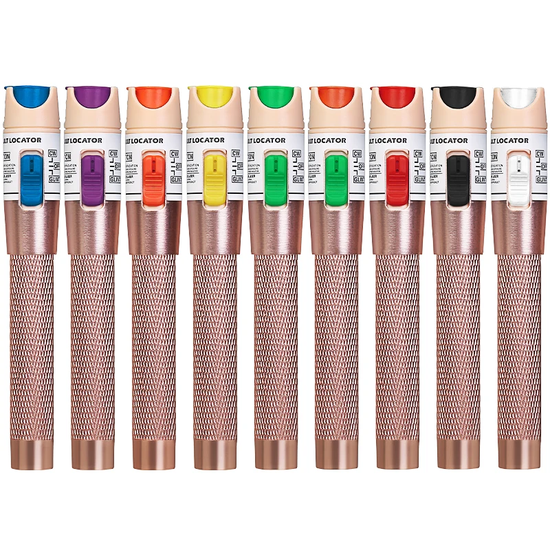
What sets a high-power visual fault locator apart from entry-level alternatives is its ability to reach deep into longer fiber runs — up to 30 kilometers in many professional-grade models — while maintaining enough optical power to illuminate faults clearly. For field technicians, network engineers, and data center professionals, the difference between a low-power and a high-power visual fault locator is not merely technical preference; it is the difference between resolving a fault in minutes versus spending hours chasing an invisible problem through kilometers of cable.
Understanding the Core Function of a Visual Fault Locator
How Visible Light Exposes Hidden Fiber Faults
A visual fault locator works by launching a continuous or pulsed 650nm red laser directly into the fiber optic core. Unlike optical time-domain reflectometers, which require interpretation of waveform data, the visual fault locator produces results that are immediately visible — a glowing red spot or a bright leak of light at the exact point of damage. This directness makes it one of the fastest diagnostic tools available in the field.
The physics behind this approach is straightforward. Where the fiber is intact, the light travels internally through total internal reflection. Where there is a break, a sharp bend, a bad splice, or a faulty connector, the light escapes from the cladding and becomes visible externally. The brighter and more powerful the laser source, the more clearly that escape point stands out, especially over longer distances or through jackets with minor transparency.
This mechanism makes the visual fault locator indispensable for verifying connector cleanliness, identifying macro-bends, confirming correct fiber polarity, and locating cable breaks along exposed or semi-exposed runs. No complex calibration or waveform reading is needed — the fault reveals itself visually.
Why Optical Power Level Matters in Fault Detection
The optical output power of a visual fault locator is typically measured in milliwatts, and professional high-power models range from 10mW to 80mW. This range has a direct impact on how far down a fiber run the locator can reliably detect a fault. A low-power model with 1mW output may be sufficient for short patch cords or in-cabinet troubleshooting, but it will fall short when the fault lies 10 or 20 kilometers down a long-haul run.
High-power visual fault locator units in the 30mW to 80mW range can penetrate significantly deeper into the cable infrastructure. The additional power compensates for natural fiber attenuation over distance, ensuring that enough light energy reaches the fault point to produce a detectable glow or leak. This is especially critical in outside plant scenarios, where cables run through conduit, trenches, or aerial spans with multiple splices along the way.
Choosing the right power level for the task is not about excess — it is about matching the tool's capability to the actual testing environment. A technician working in a campus network with short fiber spans has different requirements than one servicing a metropolitan fiber ring. The visual fault locator must be powerful enough to serve the actual use case reliably.
Key Scenarios Where a High-Power Visual Fault Locator Is Essential
Long-Distance Fiber Runs and Outside Plant Infrastructure
Outside plant fiber environments present some of the most challenging conditions for fault detection. Cables are buried, suspended, or routed through conduit over distances that can easily exceed 10 kilometers between termination points. In these settings, a low-power visual fault locator simply cannot deliver enough light energy to reach and illuminate a fault at distance. A high-power unit, by contrast, gives the technician the range needed to identify the problem without having to segment the cable or use multiple test points.
Long-haul fiber runs also tend to accumulate more splices and connector interfaces over their length. Each of these points represents a potential source of signal loss or physical damage. With sufficient optical power, a visual fault locator can confirm whether light is passing cleanly through each splice point or leaking — a distinction that is invisible at lower power levels when the escape light is too faint to observe reliably.
In restoration scenarios after cable damage from digging, weather events, or physical impact, the high-power visual fault locator allows a crew to quickly narrow the search to the damaged segment, reducing restoration time and minimizing service disruption for end users.
Data Centers, Patch Panels, and Dense Cabling Environments
Data centers may involve shorter cable runs, but the sheer density of connections creates its own set of diagnostic challenges. Dozens or hundreds of fiber patch cords may pass through the same cable management system, making it difficult to trace a specific cable path or identify which connector is causing a link failure. A visual fault locator simplifies this process by injecting visible light into the target fiber, allowing the technician to follow the light visually through the cable tray to the far end.
Connector contamination is one of the leading causes of performance degradation in data center fiber links. A high-quality visual fault locator can illuminate contaminated or damaged connectors clearly, giving technicians a fast go/no-go check before they reach for a cleaning kit or schedule a full inspection. This rapid visual check fits naturally into high-turnover data center workflows where efficiency is measured in minutes.
Polarity verification is another everyday task in dense fiber environments. With a visual fault locator, the technician injects light at one end and confirms which port the light exits at the other — a simple, reliable, and equipment-independent way to verify polarity without relying on active link testing.
Technical Features That Define a High-Power Visual Fault Locator
Universal Connector Compatibility and Adapter Design
A professional-grade visual fault locator must be compatible with the most common fiber connector types found in the field — FC, SC, and ST interfaces are the baseline expectation. Universal adapter designs allow a single unit to couple efficiently with multiple connector formats, reducing the need to carry multiple tools or purchase separate adapter kits. The 2.5mm universal adapter format, widely used in field-grade visual fault locator products, covers FC, SC, and ST connectors in one housing.
Connector interface quality matters because poor coupling wastes optical power and reduces effective range. A precision-machined adapter with low insertion loss ensures that the maximum available laser power enters the fiber, rather than being lost in the coupling gap. For high-power visual fault locator units where output power is the primary performance differentiator, preserving that output at the connector interface is essential.
Field technicians also benefit from a compact, pen-style form factor that allows one-handed operation during fault tracing. This design consideration directly affects workflow efficiency — particularly when the technician needs to trace a cable path while simultaneously holding the visual fault locator in position at the launch end.
Continuous Wave and Pulse Operating Modes
Most professional visual fault locator units offer both continuous wave (CW) and pulsed operating modes. Continuous mode is best suited for connector inspection, polarity checking, and short-distance fault location where the fault is likely to be visible in close proximity to the test point. Pulsed mode, typically operating at 1Hz or 2Hz, is preferable for longer-distance fault tracing because the pulsing light is easier to detect visually in bright ambient conditions and is more energy-efficient for extended field use.
The ability to switch between modes on a single visual fault locator extends the tool's usefulness across a wider range of tasks without requiring the technician to carry multiple instruments. In practice, a technician might use CW mode to verify a patch cord connection at the rack, then switch to pulse mode to trace a fault down a 15-kilometer outside plant run — all with the same device.
Battery life in pulsed mode is also substantially longer than in continuous mode, which matters in field environments where access to power for recharging may be limited. A high-power visual fault locator that manages battery life intelligently through mode selection gives technicians greater operational flexibility in remote or extended-work scenarios.
The Role of a Visual Fault Locator in a Complete Fiber Test Toolkit
Complementing OTDR Testing Without Replacing It
A visual fault locator and an optical time-domain reflectometer are complementary tools, not competitors. The OTDR provides detailed event maps, loss measurements, and distance-to-fault data that are essential for formal fiber certification and detailed network documentation. The visual fault locator, however, offers something the OTDR cannot — immediate, visible, real-time fault confirmation that requires no interpretation and no setup time.
In practice, many experienced technicians use the visual fault locator as a first-pass tool. If the fault is visible — a glowing bend, a leaking splice, a cracked connector — the problem can be resolved immediately without ever turning on the OTDR. This approach saves time and preserves OTDR battery life for more complex measurements. The visual fault locator earns its place in the toolkit precisely because it handles the common cases quickly, leaving the OTDR for the difficult ones.
The combination of a high-power visual fault locator with a quality OTDR and a calibrated optical power meter gives a fiber technician the full spectrum of diagnostic capability — from rapid visual inspection to precision loss measurement — suited to both reactive troubleshooting and planned network commissioning work.
Everyday Value Beyond Fault Locating
The utility of a visual fault locator extends beyond emergency fault finding. It is equally valuable during installation for confirming that fiber is correctly routed, connectors are properly seated, and splices are clean before the network goes live. Catching an installation error at this stage costs far less — in time, access, and labor — than diagnosing the same problem after the customer's network is operational.
Training new fiber technicians is another area where the visual fault locator provides real value. Its immediacy and simplicity make it an excellent teaching tool for demonstrating how fiber faults manifest physically. New technicians can develop fault-recognition skills quickly using a visual fault locator in a way that would take significantly longer with an OTDR alone.
For field service teams managing multiple sites and responding to diverse fault types, a high-power visual fault locator represents a compact, cost-effective, and reliable instrument that consistently delivers value across the full range of daily fiber maintenance activities.
FAQ
What is the effective range of a high-power visual fault locator?
High-power visual fault locator units with output levels between 30mW and 80mW can typically detect faults in fiber runs up to 30 kilometers under favorable conditions. Actual range depends on fiber type, attenuation, number of splices, and ambient lighting. In practice, shorter runs with multiple connectors or macro-bends will show faults well within this range, while long straight runs in outdoor cable may require the full available power to produce a visible signal at the fault point.
Can a visual fault locator be used on single-mode and multimode fiber?
Yes, a visual fault locator can be used on both single-mode and multimode fiber. The 650nm red laser is compatible with both fiber types, though the effective range is generally greater on single-mode fiber due to its lower attenuation characteristics. For multimode fiber, a visual fault locator is especially effective at short distances for connector inspection, continuity checking, and identifying macro-bends or physical damage in patch cords and short cable runs.
Is a visual fault locator safe to use on live fiber links?
A visual fault locator should not be connected to a live fiber link that is carrying active optical signals. Injecting additional laser light into an active fiber can interfere with live traffic and may damage sensitive optical receivers. Always confirm that the fiber under test is dark — carrying no active signal — before connecting a visual fault locator. Standard safety precautions for Class 3R laser products apply, and direct eye exposure to the laser output should always be avoided.
How does output power in milliwatts affect fault detection capability?
Output power in a visual fault locator directly determines how far the laser light can travel through the fiber before it becomes too attenuated to produce a visible escape at a fault point. Higher milliwatt ratings allow the tool to overcome natural fiber attenuation over longer distances, making faults visible at depth that would be undetectable with a lower-power unit. For technicians working on long cable runs or complex outside plant infrastructure, selecting a visual fault locator with adequate output power for the expected fiber span length is a fundamental specification decision.