What Is an OTDR and How Does It Work?
Introduction to Fiber Optic Testing
Fiber optic technology has revolutionized communication systems across the world. From high-speed internet to data centers, medical imaging, and telecommunications, fiber optics form the backbone of modern connectivity. To ensure that fiber networks perform reliably, testing tools are essential. Among these, the OTDR is one of the most critical instruments. It provides network engineers, installers, and maintenance teams with the ability to analyze, troubleshoot, and certify optical fiber systems. Understanding what an OTDR is and how it works is essential for professionals working in fiber optic communications as well as for businesses investing in robust network infrastructure.
What Is an OTDR?
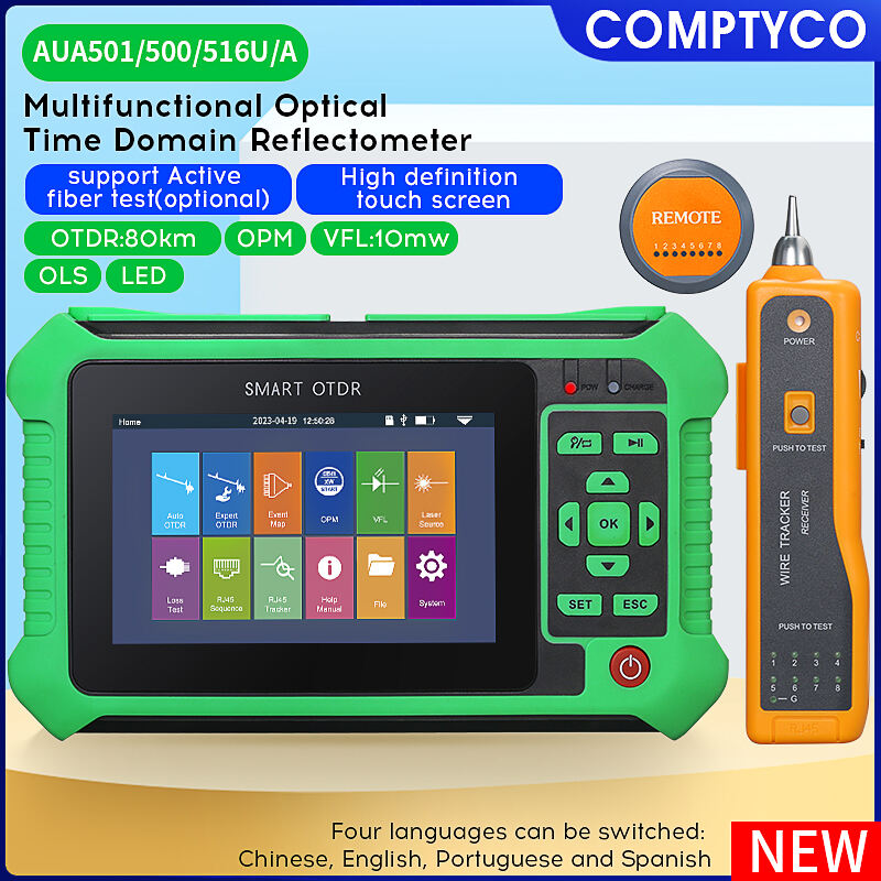
An OTDR, or Optical Time-Domain Reflectometer, is a device used to test the integrity of fiber optic cables. It works by sending pulses of light down the fiber and measuring the reflections that return from points along the cable. These reflections occur because of events such as splices, connectors, bends, breaks, or faults. The OTDR then displays this data as a trace or graphical representation, allowing technicians to pinpoint the location and severity of issues.
OTDR technology is crucial for assessing both newly installed and existing fiber optic networks. For new installations, it certifies that fibers meet performance standards. For existing networks, it helps detect and locate problems quickly, reducing downtime and maintenance costs.
Principles of OTDR Operation
Light Pulse Transmission
The OTDR generates short pulses of laser light that are injected into the fiber under test. These light pulses travel along the fiber core, encountering various events along the way.
Backscatter and Reflection
Two primary phenomena make OTDR measurement possible: Rayleigh backscatter and Fresnel reflection. Backscatter occurs when light interacts with microscopic variations in the fiber material, scattering in multiple directions, including back toward the OTDR. Fresnel reflections occur at physical discontinuities such as connectors, splices, or fiber ends, where the change in refractive index causes a portion of light to reflect back.
Time-Domain Measurement
By precisely measuring the time it takes for the reflected signals to return, the OTDR calculates the distance to each event. Since the speed of light in the fiber is known, time can be converted into distance, allowing accurate mapping of the fiber.
Trace Display
The OTDR presents results as a trace graph, showing power loss (in decibels) versus distance (in kilometers or meters). Peaks represent reflective events such as connectors, while drops represent loss events like splices or bends.
How an OTDR Works in Practice
Step 1: Setup
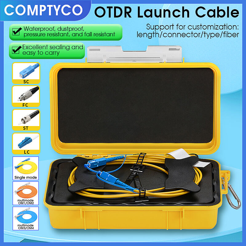
The technician connects the OTDR to one end of the fiber under test. Often, a launch cable is used between the OTDR and the fiber to allow the instrument to measure the first connector accurately.

Step 2: Test Execution
The OTDR emits a laser pulse into the fiber. Depending on the settings, it can send different pulse widths and wavelengths. Narrow pulses provide higher resolution, while wider pulses extend the measurement range.
Step 3: Data Collection
As light travels along the fiber, backscatter and reflections are captured by the OTDR’s photodetector. The instrument records the time and strength of these returned signals.
Step 4: Trace Analysis
The OTDR software processes the collected signals into a graphical trace. Technicians interpret this trace to identify and locate events such as splices, bends, connectors, or breaks.
Step 5: Reporting
Results are saved and can be exported into certification reports, which are often required for compliance with industry standards or customer acceptance of new fiber installations.
Key Functions of an OTDR
Fault Detection
An OTDR helps locate breaks, bends, and faults along the fiber. By pinpointing the exact distance of the problem, it allows quick repair with minimal disruption.
Splice and Connector Loss Measurement
Splicing fibers together or using connectors introduces signal loss. The OTDR measures the loss at each splice or connector, ensuring that it falls within acceptable limits.
Fiber Length Measurement
The OTDR provides accurate measurements of fiber length, which is essential during installation and for inventory records.
Characterization of Fiber Quality
Beyond detecting faults, OTDRs evaluate overall fiber performance, helping network operators understand long-term reliability.
Documentation and Certification
For new installations, OTDR reports provide documented proof that the network meets required specifications.
Applications of OTDR
Telecommunications
In telecom networks, OTDRs are indispensable for maintaining the reliability of long-haul and metro fiber systems.
Data Centers
High-density fiber connections in data centers require precise testing, and OTDRs help verify that connections are loss-free and compliant.
FTTx and Access Networks
For fiber-to-the-home or access networks, OTDRs allow installers to confirm that fiber runs are properly connected and free of faults.
Industrial and Military
OTDRs are also used in industries like oil and gas, aerospace, and defense, where fiber networks must remain reliable under harsh conditions.
Research and Development
In laboratories, OTDRs support the testing of new fiber designs, components, and optical systems.
Advantages of Using an OTDR
Non-Destructive Testing
OTDRs test fibers without causing damage, making them suitable for ongoing maintenance and troubleshooting.
Accurate Fault Location
They provide precise distance measurements to faults, reducing repair time and labor costs.
Comprehensive Fiber Analysis
By mapping the entire length of the fiber, OTDRs provide more detailed information than simple loss measurement devices.
Time Efficiency
They allow technicians to test long fiber spans quickly, saving significant time compared to manual inspection.
Limitations of OTDR
Dead Zones
OTDRs have limitations in measuring events close to the launch point due to dead zones, which are areas where reflective events mask nearby signals. Launch and receive cables are used to overcome this.
Resolution vs. Range Trade-Off
Short pulse widths provide higher resolution but shorter measurement range. Conversely, longer pulse widths increase range but reduce resolution.
Cost
OTDRs are more expensive than simpler fiber testers, which may limit their use to professional technicians and large-scale projects.
Complexity
Interpreting OTDR traces requires training and experience, as incorrect analysis can lead to misdiagnosis of fiber issues.
Future Developments in OTDR Technology
Miniaturization
Portable OTDRs are becoming smaller and lighter, making them easier for field technicians to use.
Enhanced User Interfaces
Modern OTDRs feature touchscreen displays, intuitive software, and automated analysis, reducing the learning curve.
Improved Accuracy
Advances in photonics and processing power continue to improve the resolution and accuracy of OTDR measurements.
Integration with Cloud Systems
Cloud-enabled OTDRs can upload results in real-time, supporting remote monitoring and faster collaboration.
AI and Automation
Artificial intelligence may soon play a role in automatic interpretation of OTDR traces, reducing the need for manual expertise.
Conclusion
The OTDR is an indispensable tool for fiber optic testing, providing detailed insight into the condition of optical fibers. By sending pulses of light into the fiber and analyzing returned reflections, it allows technicians to detect faults, measure splice and connector losses, and certify installations with precision. While it comes with limitations such as dead zones and higher costs, its ability to save time, reduce repair costs, and improve reliability makes it essential for modern communication networks. As technology advances, OTDR systems will become smarter, smaller, and more integrated, further enhancing their role in shaping the future of fiber optic communication.
FAQ
What does OTDR stand for?
OTDR stands for Optical Time-Domain Reflectometer, a device used to test fiber optic cables.
How does an OTDR locate faults?
It sends light pulses through the fiber and measures backscatter and reflections to calculate the distance to faults or events.
What is the purpose of using an OTDR in fiber optic testing?
The OTDR helps detect faults, measure splice and connector losses, verify fiber length, and certify installations.
Can an OTDR test live fiber networks?
Yes, but only with specialized filters or wavelengths. Generally, OTDR testing is performed on inactive fibers.
What are dead zones in OTDR testing?
Dead zones are areas near strong reflective events where smaller events cannot be detected. They are managed with launch and receive cables.
Is an OTDR suitable for short fiber runs?
Yes, but the instrument settings must be adjusted for short distances to ensure accurate results.
How accurate are OTDR measurements?
Modern OTDRs are highly accurate, with event location precision often within a few meters depending on settings.
What industries rely on OTDR technology?
Telecommunications, data centers, FTTx networks, industrial systems, aerospace, and defense all rely on OTDR testing.
Do OTDRs require special training to use?
Yes, interpreting OTDR traces requires knowledge and experience, though modern devices include automated analysis features.
What is the future of OTDR technology?
The future lies in miniaturization, AI-driven analysis, cloud integration, and higher accuracy for faster, more reliable fiber testing.
Table of Contents
- Introduction to Fiber Optic Testing
- What Is an OTDR?
- Principles of OTDR Operation
- How an OTDR Works in Practice
- Key Functions of an OTDR
- Applications of OTDR
- Advantages of Using an OTDR
- Limitations of OTDR
- Future Developments in OTDR Technology
- Conclusion
-
FAQ
- What does OTDR stand for?
- How does an OTDR locate faults?
- What is the purpose of using an OTDR in fiber optic testing?
- Can an OTDR test live fiber networks?
- What are dead zones in OTDR testing?
- Is an OTDR suitable for short fiber runs?
- How accurate are OTDR measurements?
- What industries rely on OTDR technology?
- Do OTDRs require special training to use?
- What is the future of OTDR technology?


