 EN
EN
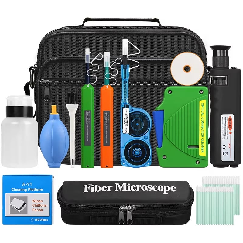
Achieving consistent low insertion loss in the field is one of the most critical challenges when deploying fiber networks. A fiber optic fast connector offers a practical solution, allowing technicians to terminate fiber on-site without the need for epoxy or polishing equipment. However, simply using a fiber optic fast connector is not enough. The way you prepare, handle, and terminate the fiber directly determines how low and consistent your insertion loss will be across every connection.
This article explains the key practices that make a fiber optic fast connector perform at its best in real field conditions. From fiber end-face preparation to mechanical alignment and final verification, each step plays a measurable role in reducing signal loss. Whether you are working on FTTH drops, enterprise cabling, or rapid network expansion, understanding these principles will help you terminate fiber reliably and efficiently every time.
Why End-Face Preparation Defines Connector Performance
The Role of the Cleave in Every Fiber Optic Fast Connector
The single most important step when using a fiber optic fast connector is producing a clean, flat fiber cleave. The mechanical splice inside a fiber optic fast connector relies on gel or index-matching material to bridge two fiber end-faces. If one end-face has an angled fracture, chips, or surface contamination, that irregularity creates an air gap and increases reflection and scattering loss. A high-quality fiber optic fast connector can only perform as well as the cleave it receives. Consistently achieving a cleave angle below one degree is the baseline standard most fiber optic fast connector designs require.
Using a precision cleaving tool designed for field use makes this step repeatable. Many fiber optic fast connector kits include a matched cleaver to ensure compatibility with the required fiber strip length and cleave quality. Never re-use a dull cleaving blade. A degraded blade introduces micro-cracks into the fiber end-face that are invisible to the naked eye but immediately detectable in loss measurements. Replacing the blade at the manufacturer-recommended interval maintains consistent cleave quality across every fiber optic fast connector you install.
Stripping and Cleaning Before Termination
Before a fiber optic fast connector can be seated, the fiber must be properly stripped and cleaned. Residual coating material on the bare glass will prevent the fiber from seating flush inside a fiber optic fast connector, which raises insertion loss above acceptable levels. Use a thermal or mechanical stripper calibrated for the specific fiber diameter and coating type. After stripping, wipe the bare fiber with an IPA-saturated lint-free tissue in a single outward motion. Reusing the same section of tissue redeposits contamination onto the fiber, which is a common but preventable cause of high loss in fiber optic fast connector terminations.
Mechanical Alignment and Connector Handling Techniques
Inserting Fiber into a Fiber Optic Fast Connector Correctly
Once the fiber is prepared, the insertion technique into the fiber optic fast connector housing is critical. Most fiber optic fast connector designs feature a pre-installed stub fiber on one side of the internal mechanical splice. The field-installed fiber must reach this stub to form a continuous optical path. Always insert the cleaved fiber slowly and steadily, applying light forward pressure until you feel the defined stop point inside the fiber optic fast connector. Stopping short of this point leaves a gap between the field fiber and the stub, which is a direct source of insertion loss that cannot be corrected after the fiber optic fast connector is locked.
Some fiber optic fast connector designs include a visual indicator or a physical click to confirm proper fiber seating. Always verify this before locking the fiber optic fast connector mechanism. Locking the connector without confirmation is a common field error that results in high loss measurements and requires the entire fiber optic fast connector to be replaced rather than adjusted. Taking three extra seconds at this stage eliminates a disproportionate number of failed terminations.
Controlling Fiber Bend Radius During Termination
Bending the fiber too sharply near the entry point of a fiber optic fast connector causes stress at the mechanical splice interface. This stress introduces microbend loss that adds to insertion loss unpredictably. Keep the fiber path straight and relaxed for at least 30 millimeters behind the fiber optic fast connector entry boot. When routing fiber after installation, always observe the minimum bend radius for the cable type in use. A fiber optic fast connector termination that tests perfectly at the workbench can show elevated loss in the finished installation if the cable is bent tightly behind the connector housing.
Verification and Troubleshooting After Installation
Using an Optical Power Meter with Every Fiber Optic Fast Connector
Every fiber optic fast connector installation should be verified with an optical power meter before the link is declared complete. Testing confirms that the fiber optic fast connector is within the accepted insertion loss budget for the link. Typical field-installable fiber optic fast connector designs achieve insertion loss between 0.2 dB and 0.5 dB when properly installed. A reading above 0.5 dB on a fiber optic fast connector suggests a preparation or insertion error and the connector should be replaced. Recording test results for each fiber optic fast connector creates a documented audit trail that simplifies future troubleshooting.
Using a Visual Fault Locator to Confirm Continuity
A visual fault locator is a fast and effective complementary tool for every fiber optic fast connector check. It emits visible red light through the fiber, making breaks, high-loss joints, and poorly seated fiber optic fast connector terminations visible as bright spots through the cable sheath or connector housing. Before using an optical power meter for precise loss measurement, a visual fault locator confirms that the fiber optic fast connector has basic continuity and that the fiber is not broken at the mechanical splice point. Combining both tools as a standard workflow ensures no fiber optic fast connector leaves the installation site untested.
FAQ
What is the typical insertion loss for a properly installed fiber optic fast connector?
A correctly terminated fiber optic fast connector typically produces insertion loss between 0.2 dB and 0.5 dB. Achieving results at the lower end of this range depends on cleave quality, fiber cleanliness, and proper seating inside the fiber optic fast connector housing. Loss values above 0.5 dB usually indicate a preparation or insertion error.
Can a fiber optic fast connector be re-used if the first termination fails?
Most fiber optic fast connector designs are intended for single-use termination. Once the internal locking mechanism of a fiber optic fast connector is engaged, the fiber cannot be withdrawn and re-inserted reliably. Attempting to reuse a locked fiber optic fast connector typically results in higher loss or physical damage to the internal stub fiber. Replacing the fiber optic fast connector is the recommended action when a termination fails testing.
Which fiber types are compatible with a standard fiber optic fast connector?
Most standard fiber optic fast connector products are designed for single-mode or multimode fiber with 125-micron cladding diameter. Always verify compatibility between the fiber optic fast connector model and the specific fiber type before beginning installation. Using a fiber optic fast connector rated for single-mode fiber on a multimode cable, or vice versa, will produce excessive insertion loss and should be avoided.